
Processing technique of annular thin wall part

A technology for processing thin-walled parts and thin-walled parts, which is applied in the direction of metal processing equipment, metal processing machinery parts, manufacturing tools, etc., can solve the problems of low pass rate of workpiece processing, elastic deformation of parts, and inability to meet processing accuracy, etc. Process reliability, effect of reducing deformation

Inactive Publication Date: 2008-12-31
SHANGHAI MARITIME UNIVERSITY
View PDF0 Cites 41 Cited by
  • Summary
  • Abstract
  • Description
  • Claims
  • Application Information

AI Technical Summary

Problems solved by technology

Due to the lack of rigidity of the parts themselves and the excess of flexibility, conventional clamping not only fails to meet the processing accuracy, but also causes shape errors due to the elastic deformation of the parts due to the clamping force, and the processing pass rate of the workpiece is low. difficulty

Method used


Image

  • Processing technique of annular thin wall part
  • Processing technique of annular thin wall part
  • Processing technique of annular thin wall part

Examples


Embodiment 1

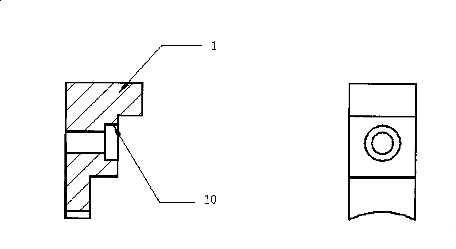
[0042] Embodiment 1. The making of soft three claws 1

[0043] Material:

[0044] The soft three-claw material is ordinary aluminum, LY12. This material is lightweight and cheap. When turning, it is not easy to "eat the knife" to wear the cutting edge. Especially in high-speed cutting and small feed rate, it is easier to obtain a smooth surface, and it is an ideal tooling material.

[0045] The principle and production of soft three claws:

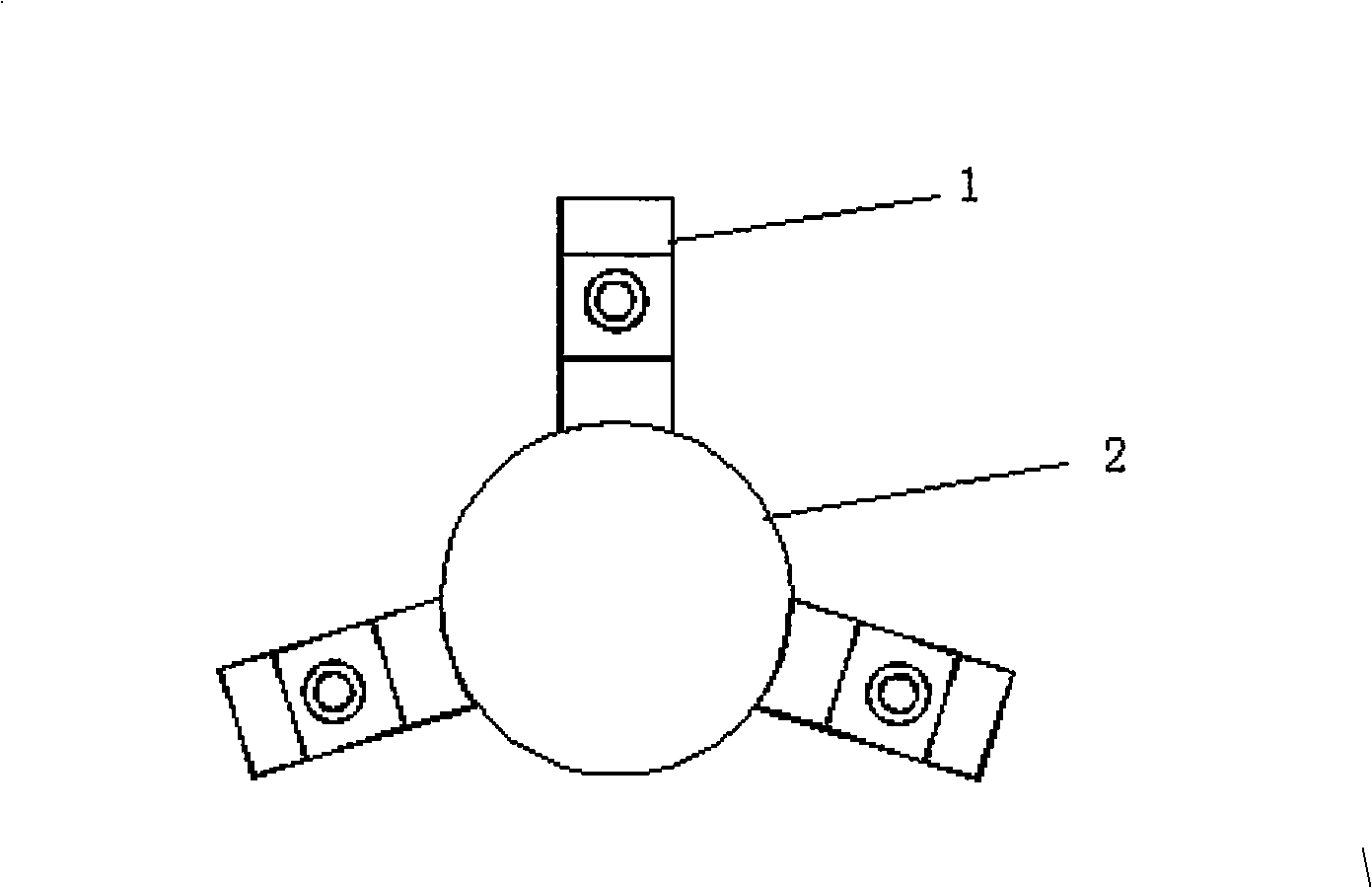
[0046] Since the clamping surface of the jaws of the ordinary three-jaw chuck is not the same surface, the workpiece cannot be guaranteed to be in the same central position during the two clamping processes. Therefore, if the workpiece is directly clamped on the three-jaw chuck of the lathe, it will inevitably affect its coaxiality.

[0047] The soft three-jaw is fixed on the three-jaw chuck by screws. The center hole (for clamping the mandrel) is machined by the lathe. In this way, after the workpiece is put on the mandrel, the acc...

Embodiment 2

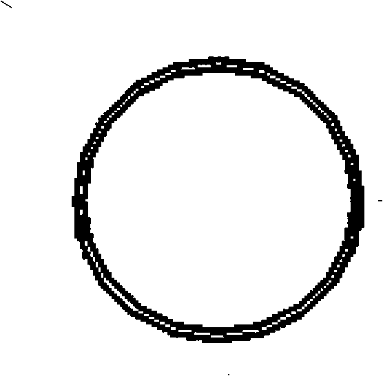
[0049] Embodiment 2. Annular thin-walled sleeve processing

[0050] Annular thin-walled sleeve such as image 3 , Figure 4 Shown:

[0051] Material: 1Cr18Ni9Ti;

[0052] Outer diameter: Φ72mm;

[0053] Inner diameter: Φ68.6(+0.02 / 0)mm;

[0054] Workpiece width 8mm;

[0055]The ratio of outer diameter to wall thickness is 72 / 1.7=42.35;

[0056] Coaxiality 0.05mm.

[0057] Processing steps:

[0058] 1. Outer diameter of the upper mandrel

[0059] The direct positioning of the workpiece is changed, and the positioning of the workpiece through the tooling does not cause the workpiece to be clamped and deformed. Therefore, the design and production of tooling is very critical.

[0060] Tooling material: brass (H62) for the mandrel, mandrel sleeve, outer cover and locking cover. Due to the low hardness of this material, the friction coefficient is also small, and it has self-lubricating properties especially in high-speed machining (that is, no need Adding cutting fluid ...


PUM


Abstract

The invention relates to a processing technology for an annular thin-walled part, which is characterized in that the annular thin-walled workpiece to be processed is sheathed on a core shaft sleeve which is processed from a core shaft and clamped in a clamp mouth of a soft three-jaw fixed on a three-jaw chuck by screws, the annular end face of the workpiece to be processed is contacted and locked with an outer cover plate or a locking cover plate, the outside and inside diameters are processed by a lathe, the workpiece is tailored by the steps, the core shaft sleeve is sheathed into the inside diameter of an annular thin-walled sleeve to improve the rigidity of the annular thin-walled sleeve during processing, and the locking cover plate is contacted with the annular end face of the processed workpiece to ensure that the workpiece does not bear external radial force. The processing technology effectively ensures the processing accuracy of the annular thin-walled part, and improves the processing qualification rate of the workpiece, which meets the designed dimensional requirements.

Description

technical field [0001] The invention relates to a processing technology suitable for processing annular thin-walled parts and special processing equipment used therein. technical background [0002] At present, the volume of mechanical products tends to be miniaturized, and the parts are also developing in the direction of "small", "thin" and "light". Therefore, more and more thin-walled parts and thin-shaped parts are encountered in processing. Thin-walled parts are a kind of parts that are difficult to machine in machining. Among them, the annular thin-walled sleeve is a typical part in thin-walled parts. Due to the lack of rigidity of the parts themselves and the excess of flexibility, conventional clamping not only fails to meet the processing accuracy, but also causes shape errors due to the elastic deformation of the parts due to the clamping force, and the processing pass rate of the workpiece is low. difficulty. Contents of the invention [0003] The object of ...

Claims


Application Information

Patent Timeline
IPC IPC(8): B23B1/00B23B5/00B23Q3/14B23B31/02
Inventor 季明浩
Owner SHANGHAI MARITIME UNIVERSITY
Learn More