Expansion machine rotor for highly pressurized liquid throttling

A high-pressure liquid and expander technology, which is applied in the direction of reaction engines, mechanical equipment, engine components, etc., can solve the problems of high requirements and large volume of liquid expanders, and achieve energy consumption reduction, flexible braking methods, and realization of The effect of high-power high-speed transmission

Active Publication Date: 2011-08-31
XI AN JIAOTONG UNIV +1
View PDF1 Cites 2 Cited by
  • Summary
  • Abstract
  • Description
  • Claims
  • Application Information

AI Technical Summary

Problems solved by technology

But the liquid expander of Ebara Company has the following disadvantages: 1) the structure of the runner and the generator being coaxial and in the same housing is adopted, the runner needs to be equivalent to the size of the generator, and the liquid expander has a large volume, which is only suitable for large flow Applications (such as throttling and pressure reduction of large natural gas liquefaction plants); 2) The generator needs to be immersed in liquefied gas, which has high requirements for generator materials and manufacturing technology; 3) It is not suitable for other forms of braking, such as Fans, pumps, etc.

Method used


Image

  • Expansion machine rotor for highly pressurized liquid throttling
  • Expansion machine rotor for highly pressurized liquid throttling
  • Expansion machine rotor for highly pressurized liquid throttling

Examples


Embodiment Construction

[0021] The present invention will be described in further detail below in conjunction with the accompanying drawings and embodiments.

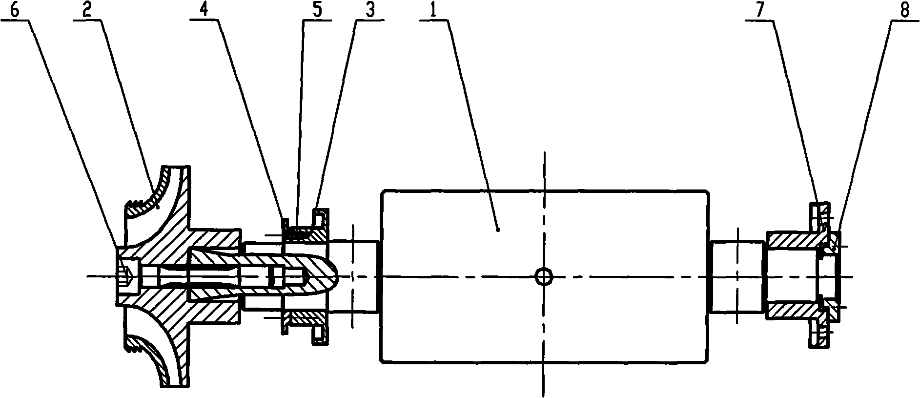
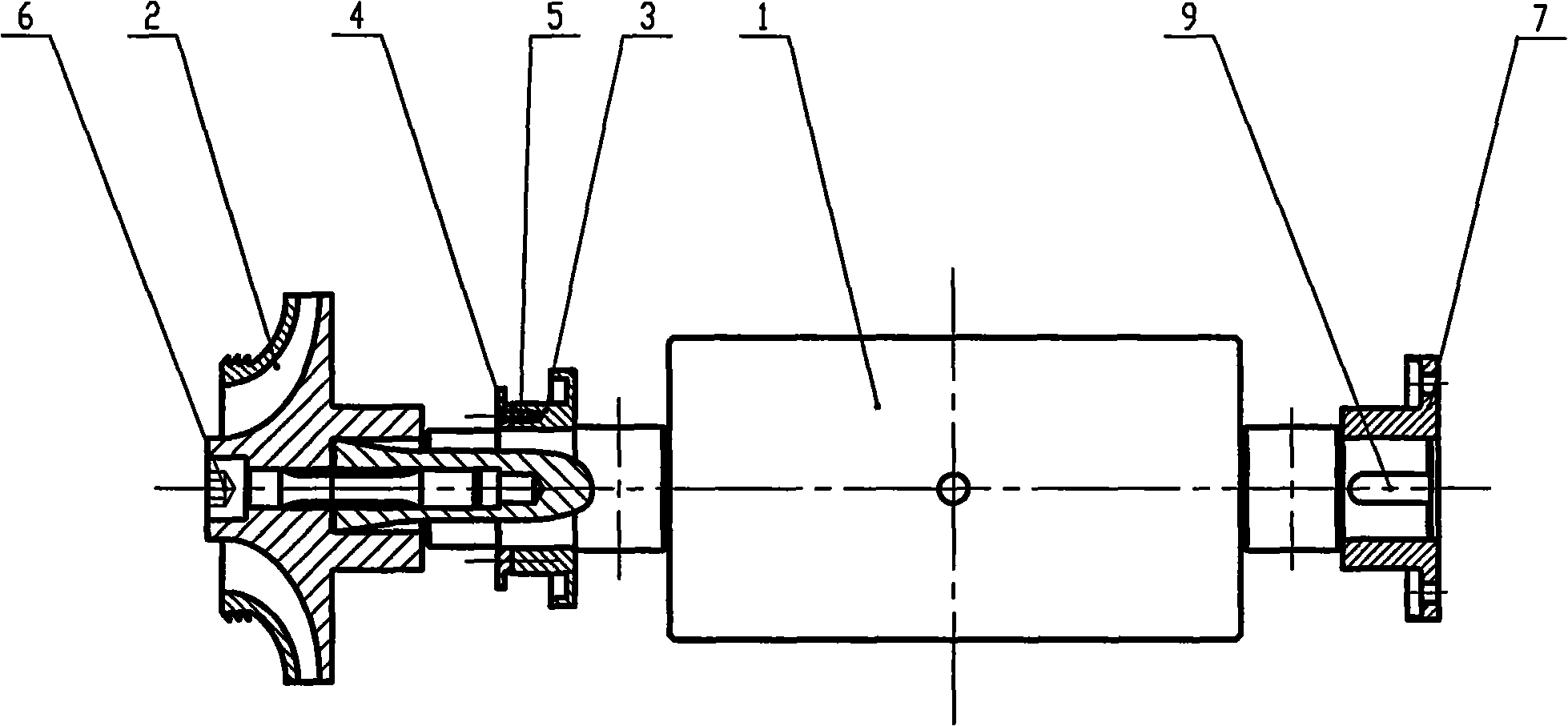
[0022] like figure 1 and figure 2 As shown, two examples of a liquid expander rotor, such as figure 1 In the example of the rotor shown, the main shaft 1 at the gearbox end is connected with the diaphragm coupling 7 through a triangular shaft and fixed with a fastening nut 8 . like figure 2 In the rotor example shown, the main shaft can also be connected to the diaphragm coupling 7 via a key 9 . The oil throwing ring 3 and the oil throwing ring baffle 4 are fixed by the hexagon socket head screw 5 .

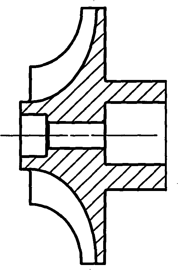
[0023] The impeller 2 adopts a radial flow centripetal impeller, which can be a closed structure or a semi-open structure ( image 3 ), or fully open structure ( Figure 4 ). There is a triangular hole at the center line of the impeller, which is connected with the triangular journal of the main shaft. The impeller radially enters the l...


PUM


Abstract

The invention discloses an expander rotor used for throttling high pressure liquid, which comprises an impeller and a main shaft. The expander rotor is characterized in that the rotor adopts an impeller cantilever horizontal type structure; one end of the main shaft is an impeller end, and the other end thereof is a gearbox end; the main shaft impeller end adopts an axis tripod connection method and is connected with the impeller to generate shaft work, and the main shaft gearbox end is connected with the gearbox through a high speed transmission mechanism to realize the transmission of the shaft work; an axial force balancing mechanism are arranged at the position of the shaft shoulders at both ends of the main shaft; a bearing mechanism is arranged on the shaft neck at the outer side ofthe shaft shoulders at the both ends of the main shaft. The rotor can solve the hard requirements of the prior liquid expander for the media flow quantity and the braking process of the generator, common generators, pumps or blower fans can be adopted to perform braking, the rotor is suitable for the media pressure reduction with arbitrary flow quantities, and both the energy conservation and theconsumption reduction effects are obvious.

Description

technical field [0001] The invention relates to a liquid expander device for throttling and reducing pressure, in particular to a liquid expander rotor. Background technique [0002] In the process flow of the air separation liquefaction unit, the high-pressure liquefied gas needs to be throttled and depressurized to meet the requirements of the subsequent process. Usually, the pressure of tens of atmospheres must be reduced to several atmospheres. At present, the traditional coke-soup liquid throttle valve is generally used to complete the pressure reduction, which causes irreversible loss of liquid high-pressure energy and induces vaporization, resulting in reduced gas extraction rate and cavitation damage. Taking the internal compression air separation process as an example, the vaporization rate of the high-pressure liquid reaches 10-20% after throttling to the lower tower through the coke-soup valve, and the vaporization rate even exceeds 30% after throttling to the upp...

Claims


Application Information

Patent Timeline
Patent Type & Authority Patents(China)
IPC IPC(8): F03B3/02F03B11/06F03B3/12F01D5/02F01D25/16F01D5/14
CPCY02E10/226Y02E10/223Y02E10/20
Inventor 孙金菊李成韩春明李心伟蔡国成马国红
Owner XI AN JIAOTONG UNIV
Why Eureka
Try Eureka