
Method for measuring attosecond pulse width

A pulse and attosecond technology, applied in the field of measuring the pulse width of attosecond pulses, can solve the problems of low attosecond pulse intensity, complexity, lack of nonlinear phenomenon, etc., achieve simple and accurate measurement methods, simplify measurement methods, and avoid fitting calculations Effect

Inactive Publication Date: 2008-12-31
HUAZHONG UNIV OF SCI & TECH
View PDF0 Cites 13 Cited by
  • Summary
  • Abstract
  • Description
  • Claims
  • Application Information

AI Technical Summary

Problems solved by technology

Among them, due to the low intensity of attosecond pulses and the lack of nonlinear phenomena required for measurement in the extreme ultraviolet region, there are still many difficulties in measuring single attosecond pulses using the autocorrelation method
The use of correlation crossover technology is currently a relatively common method for measuring single attosecond pulses. This method uses femtosecond lasers as a reference time, and obtains the pulse width of attosecond pulses by fitting the energy drift or broadening of the photoelectron spectrum with phase changes. This method is very complicated, requiring not only a series of photoelectron spectra, but also a large number of fitting calculations
So far, a direct quantum relationship between photoelectron spectra and single attosecond pulses has not been established

Method used


Image

  • Method for measuring attosecond pulse width
  • Method for measuring attosecond pulse width
  • Method for measuring attosecond pulse width

Examples


example 1

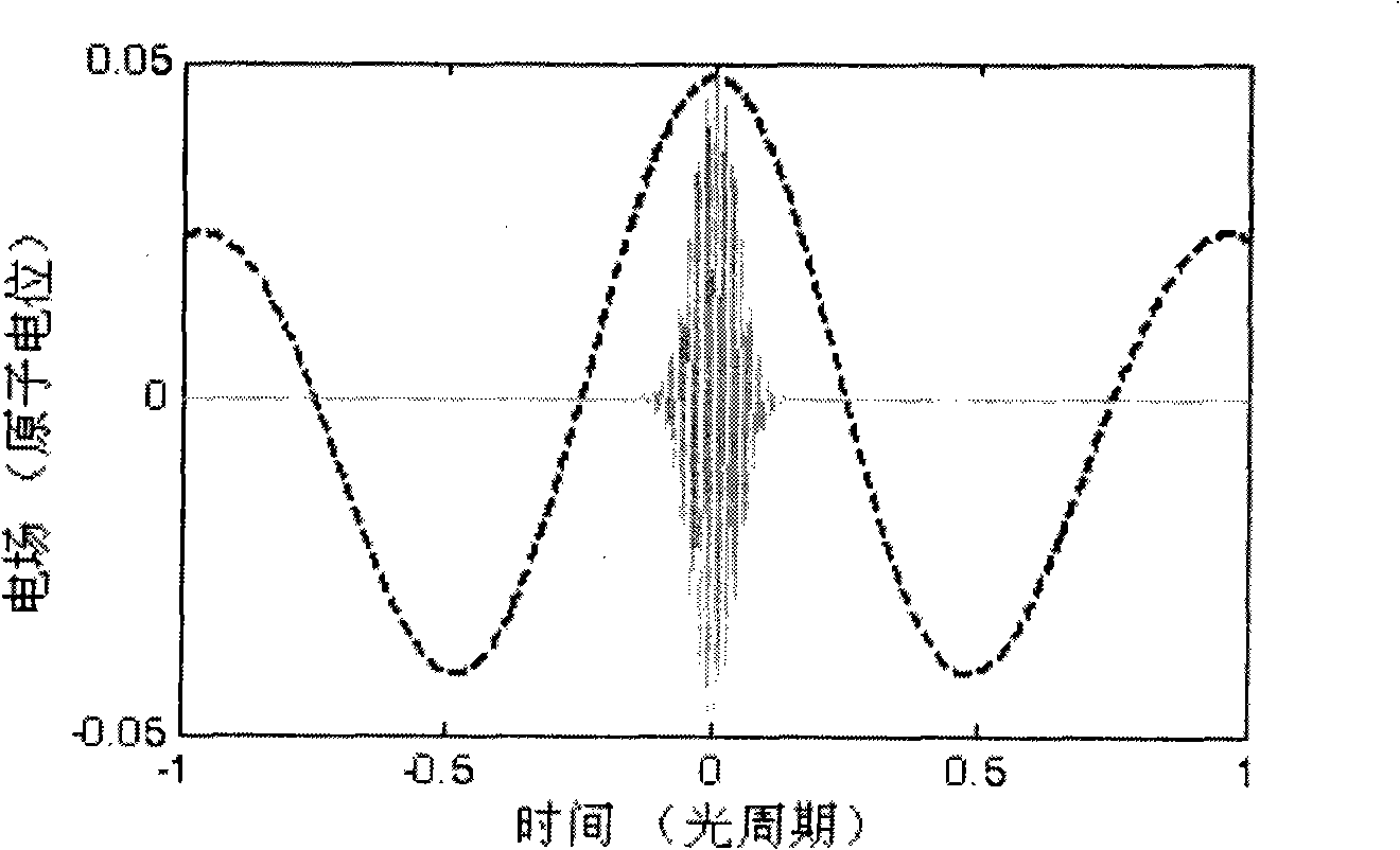
[0017] The rare gas used is helium, and the laser intensity is 8×10 13 Wcm -2 , the wavelength is 800nm. The attosecond pulse intensity is 5×10 12 Wcm -2 , (attosecond pulse) angular frequency is 3.42a.u. The laser field converts the attosecond pulse into a photoelectron signal through single-photon ionization, and collects the photoelectron signal to obtain a photoelectron spectrum containing the attosecond pulse information. Establish a precise relationship between the photoelectron spectrum and the attosecond pulse, as shown in the above relational formula, which uses atomic units, where ΔE represents the spectral width of the photoelectron energy spectrum, and the mass kinetic energy U p = eE 2 4 ω 0 2 , E is the electric field amplitude, ω ...

example 2

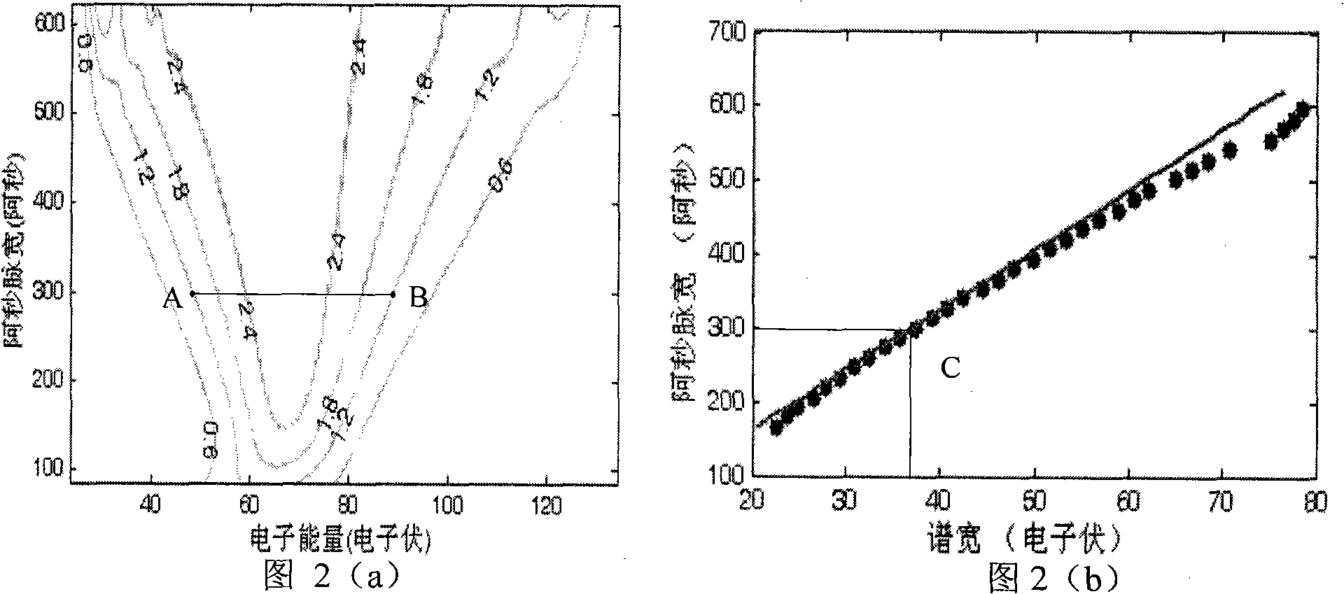
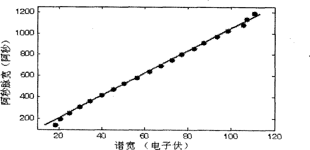
[0020] The rare gas used is helium, and the laser intensity is 5×10 13 Wcm -2 , the wavelength is 1600nm, the attosecond pulse intensity is 5×10 12 Wcm -2 , (attosecond pulse) angular frequency is 3.42a.u. The laser field converts the attosecond pulses into photoelectron signals through single-photon ionization, and the final photoelectron spectrum inherits the information of the attosecond pulses. According to the formula of relation image 3 The curve indicated by the solid line, image 3 The dotted line and the solid line in are respectively the photoelectron spectrum diagram and the attosecond pulse width and the photoelectron spectral width relationship diagram obtained by solving the time-dependent Schrödinger equation and the method in the present invention, and the photoelectric spectral width measured in the experiment can then be Depend on image 3 The corresponding attosecond pulse width is obtained from the curve. By comparison, the results obtained by the t...


PUM


Abstract

The invention relates to a method for measuring the pulse width of attosecond pulse, including the following steps: 1) beam combining light composed of laser and the attosecond pulse is focused on a noble gas, and formed into a photoelectronic signal containing attosecond pulse information by single photon ionization; 2) the photoelectronic signals are collected to obtain a photoelectron spectrum; 3) the photoelectron spectrum is analyzed by utilizing the relational formula of the photoelectron spectrum and the attosecond pulse so as to obtain the pulse width of the attosecond pulse. The method of the invention establishes the direct relation between the photoelectron spectrum and the attosecond pulse, and obtains the pulse width of the attosecond pulse by measuring the photoelectron spectral width; the proposal simplifies the measuring method and avoids massive fitting computation, and the measuring result is precise.

Description

technical field [0001] The invention relates to a method for measuring attosecond pulse width. Background technique [0002] With the development of ultrafast technology, the intense laser pulse is shortened continuously, and its pulse width has reached the order of photoperiod. This cycle-scale laser pulse (about 5 femtoseconds) interacts with atoms, making a new breakthrough in the generation of shorter pulses, and a single attosecond pulse has been realized. Attosecond pulses can realize real-time measurement and control of electron motion in atoms and molecules, which has attracted increasing attention in recent years. Single attosecond pulses have been used to observe the evolution process of atomic inner core, electron tunnel ionization and control the generation of higher harmonics. All of these applications rely on single attosecond pulses and are therefore very important to measure attosecond pulses. [0003] At present, there are roughly two methods for measurin...

Claims


Application Information

Patent Timeline
Patent Type & Authority Applications(China)
IPC IPC(8): G01J11/00
Inventor 陆培祥兰鹏飞王少义李芳杨振宇
Owner HUAZHONG UNIV OF SCI & TECH
Learn More