Reflecting type full-optical fiber current sensor
A current sensor, all-fiber technology, applied in voltage/current isolation, measuring current/voltage, instruments, etc., can solve problems affecting the measurement accuracy of transformers, and achieve the effect of reducing polarization noise and improving measurement accuracy
- Summary
- Abstract
- Description
- Claims
- Application Information
AI Technical Summary
Problems solved by technology
Method used
Image

Examples
Embodiment 1
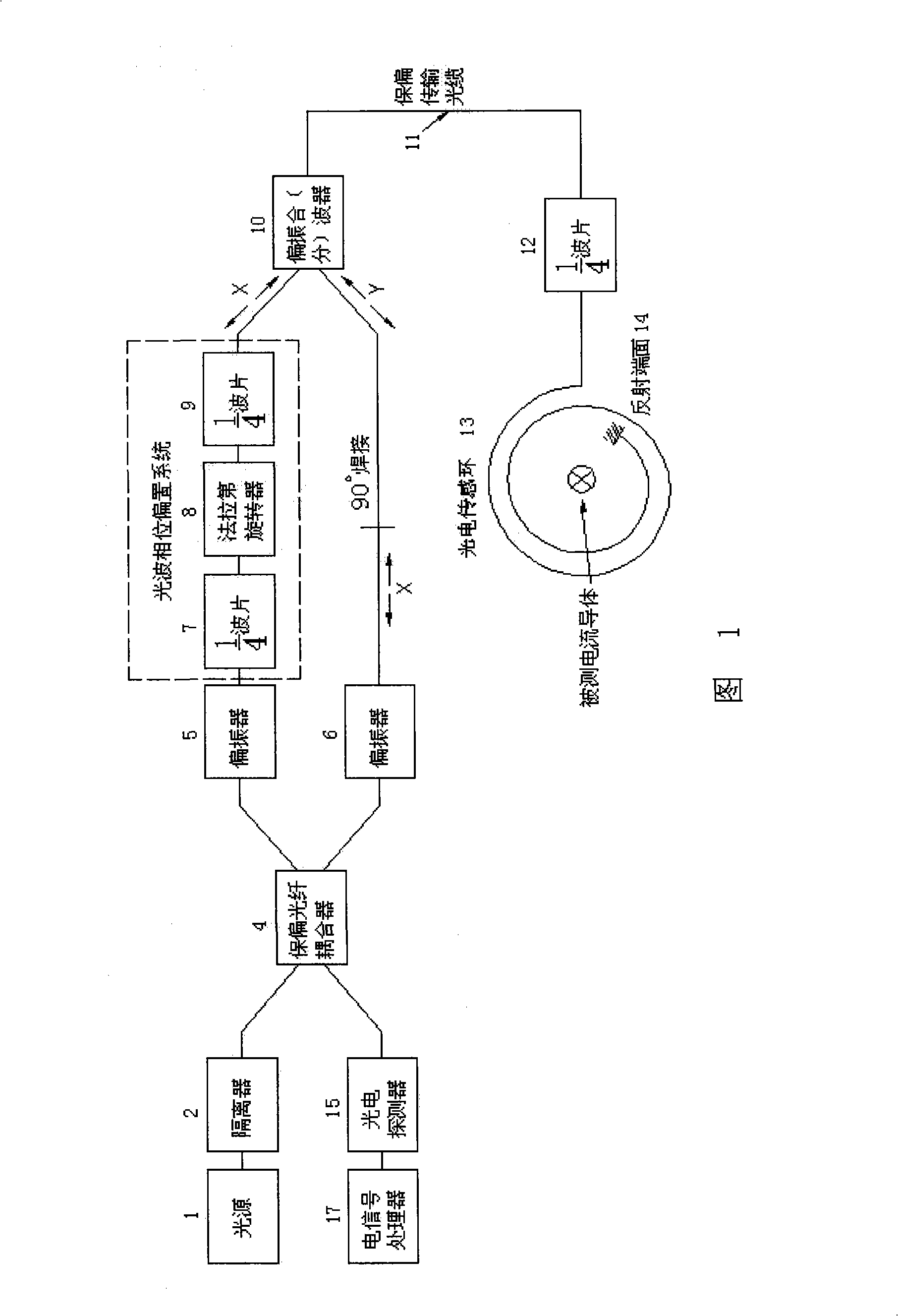
[0024] Embodiment 1: Referring to Fig. 1, the structure and working principle of the reflective interference type all-fiber current sensor are as follows: the light wave enters the polarization-maintaining fiber coupler 4 after passing through the isolator 2 from the light source 1, and its two forward output terminals are respectively connect After polarizers 5 and 6, the two paths of light are linearly polarized light polarized in the x direction. where the polarizer 5 outputs xThe linearly polarized light in the direction becomes circularly polarized light after passing through the first 1 / 4 wave plate 7 in the light wave phase bias system, and then after passing through the Faraday rotator 8, the circularly polarized light is rotated by 45 degrees, and the circularly polarized light In terms of light, the space is rotated by 45 degrees, which means that there is a phase difference of 45 degrees in time. When it is restored to linearly polarized light in the x direction by...
Embodiment 2
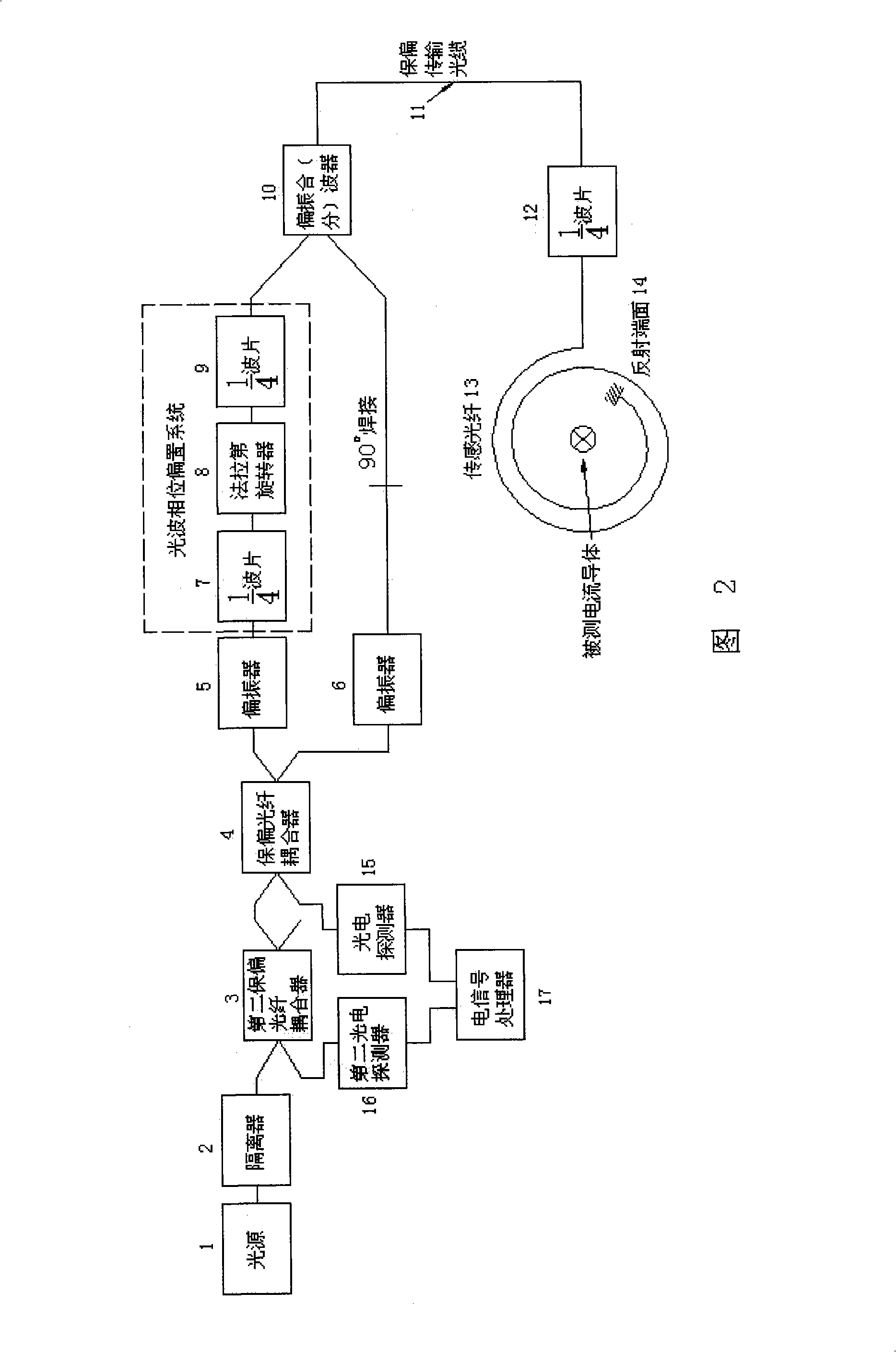
[0025] Embodiment 2: Referring to Fig. 2, the reflective all-fiber current sensor is based on Embodiment 1, and the complementary signal output to the other port after the interference of the polarization-maintaining fiber coupler 4 is sent by the second polarization-maintaining fiber coupler 3 Take out half of it for detection and signal processing, so that although the signal will be half larger, the input optical power will be lost by half.
Embodiment 3
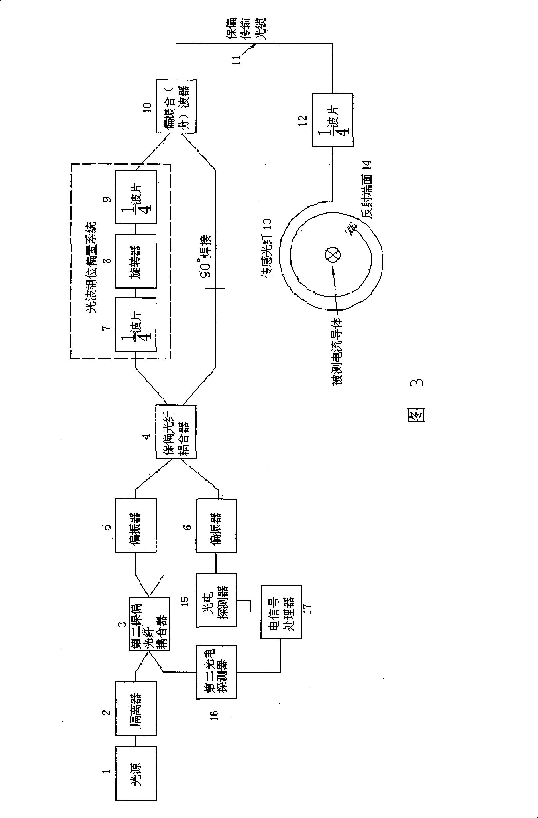
[0026] Embodiment 3: Referring to FIG. 3 , this reflective all-fiber current sensor is based on Embodiment 2, and the positions of the two polarizers 5 and 6 are changed, and the effect is the same as that in FIG. 2 . It is also possible to change the coupler 4 and the two polarizers 5 and 6 in FIG. 2 into a planar optical waveguide Y-type splitter. Since the planar optical waveguide itself acts as a polarizer, the effect is the same.
PUM
 Abstract
Description
Claims
Application Information
 - R&D
- Intellectual Property
- Life Sciences
- Materials
- Tech Scout
- Unparalleled Data Quality
- Higher Quality Content
- 60% Fewer Hallucinations
Browse by: Latest US Patents, China's latest patents, Technical Efficacy Thesaurus, Application Domain, Technology Topic, Popular Technical Reports.
© 2025 PatSnap. All rights reserved.Legal|Privacy policy|Modern Slavery Act Transparency Statement|Sitemap|About US| Contact US: help@patsnap.com