Network intelligent wireless control system

A wireless control and network intelligence technology, applied in transmission systems, instruments, data exchange through path configuration, etc., can solve problems such as interference, false alarms, and inability to understand user conditions in time

Inactive Publication Date: 2008-12-31
邱柏康 +1
View PDF0 Cites 25 Cited by
  • Summary
  • Abstract
  • Description
  • Claims
  • Application Information

AI Technical Summary

Problems solved by technology

[0003] 1. Since the single base station in the prior art wireless alarm system is only a single monitoring device installed in each user unit, although the user can keep abreast of the monitoring information at home, the property management or monitoring center of the residential area cannot monitor the monitoring information of all users. Centralized and unified management of monitoring information, unable to keep abreast of the situation of each user's home, so that the alarm cannot be processed in the first time;
[0004] 2. Due to the existing technology, the base station signal transceiver that receives the alarm signals sent by various types of collectors, that is, the alarm equipment, must be sent by the processor chip of the microcomputer according to the various types of alarm monitoring equipment connected to it during installation and debugging. The signal is programmed, modulated and stored in the numbered seat, that is, each alarm monitoring device needs to have a specific interface, so the existing wireless alarm system has the defects of high operating cost and unreliable communication network
[0005] 3. Since the base station signal transceiver in the wireless alarm control system of the prior art adopts the method of passively receiving the alarm signal, that is, the base station signal transceiver itself has no monitoring function, but only when the alar

Method used


Image

  • Network intelligent wireless control system
  • Network intelligent wireless control system
  • Network intelligent wireless control system

Examples


Embodiment Construction

[0036] The present invention will be further described below in conjunction with accompanying drawing and specific embodiment:

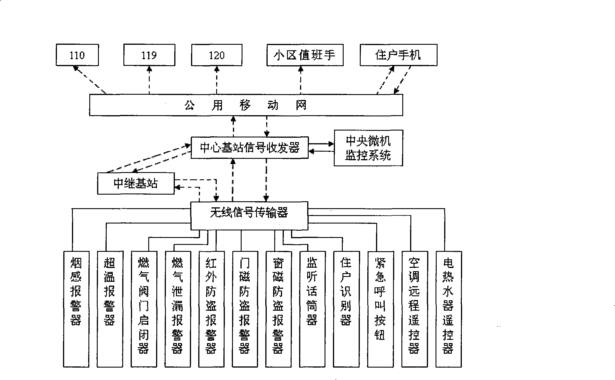
[0037] Such as figure 1 As shown, the network intelligent wireless control system of the present invention includes various types of alarm monitoring equipment and electrical equipment installed in the user unit, a central base station set in the property management center or monitoring center of the community, and a central base station set in the user unit with the ability to actively search for various types of alarms. Monitoring equipment and electrical equipment, and can detect the working status of various alarm monitoring equipment and electrical equipment in time and send the detected data to the wireless signal transmitter of the central base station in time; the central base station includes a GPRS module The central base station signal transceiver and the central microcomputer monitoring system connected with the central base station signa...


PUM


Abstract

The invention discloses an actively-homing network intelligent wireless control system which is based on a ZigBee network control technology and can realize remote automation control for such fields as family digitalization, industry and intelligent transportation; the system comprises a collector arranged in a user unit, a wireless signal transmitter connected to a control relay of the power switch of the collector, and a central base station that is arranged in a monitoring center and is connected to alarming units and mobile phone signals of users through a public mobile network; the protocol between the wireless signal transmitter and a signal transreceiver of the central base station is the ZigBee wireless protocol. The invention can not only realize the concentralized management of monitoring signals of the user unit, timely understand the conditions of the user unit and process the conditions in the first time, but also actively search the collector, electric appliances and a machine to realize trouble monitoring and remote control of various collectors and electric equipment; the system of the invention has the advantages of low operation cost, safe and reliable communication network, but no such phenomena as false alarm, seton or interference.

Description

Technical field: [0001] The invention relates to a network intelligent wireless control system, specifically a network intelligent wireless control system capable of actively seeking and realizing remote automatic control of various collectors, namely alarm monitoring facilities and various electrical appliances. Background technique: [0002] At present, the wireless alarm control system in the prior art generally adopts a passive receiving mode controlled by a single base station. Each base station is an isolated system. In other words, each user unit is an independent control base station. This independent control base station Set in each user unit, it is connected by a base station signal transceiver and various collectors such as smoke alarms, gas leakage alarms, door magnetic anti-theft alarms, etc. using wired RS485 connection or wireless signal connection; the base station signal The transceiver is embedded with a GPRS module; the various types of alarm equipment are...

Claims


Application Information

Patent Timeline
IPC IPC(8): G08B25/10G08B27/00H04L12/28H04L29/08
Inventor 邱柏康王小军熊伟
Owner 邱柏康
Why Eureka
Try Eureka