

Sealed battery and manufacturing method therefor
A manufacturing method and a sealed technology, applied in the direction of battery pack parts, final product manufacturing, sustainable manufacturing/processing, etc., can solve problems such as a large amount of welding energy, and achieve good efficiency, high reliability, and firm efficiency
- Summary
- Abstract
- Description
- Claims
- Application Information
AI Technical Summary
Problems solved by technology
Method used
Image

Examples
Embodiment 2
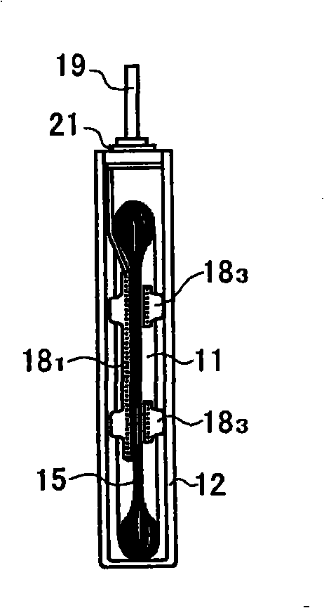
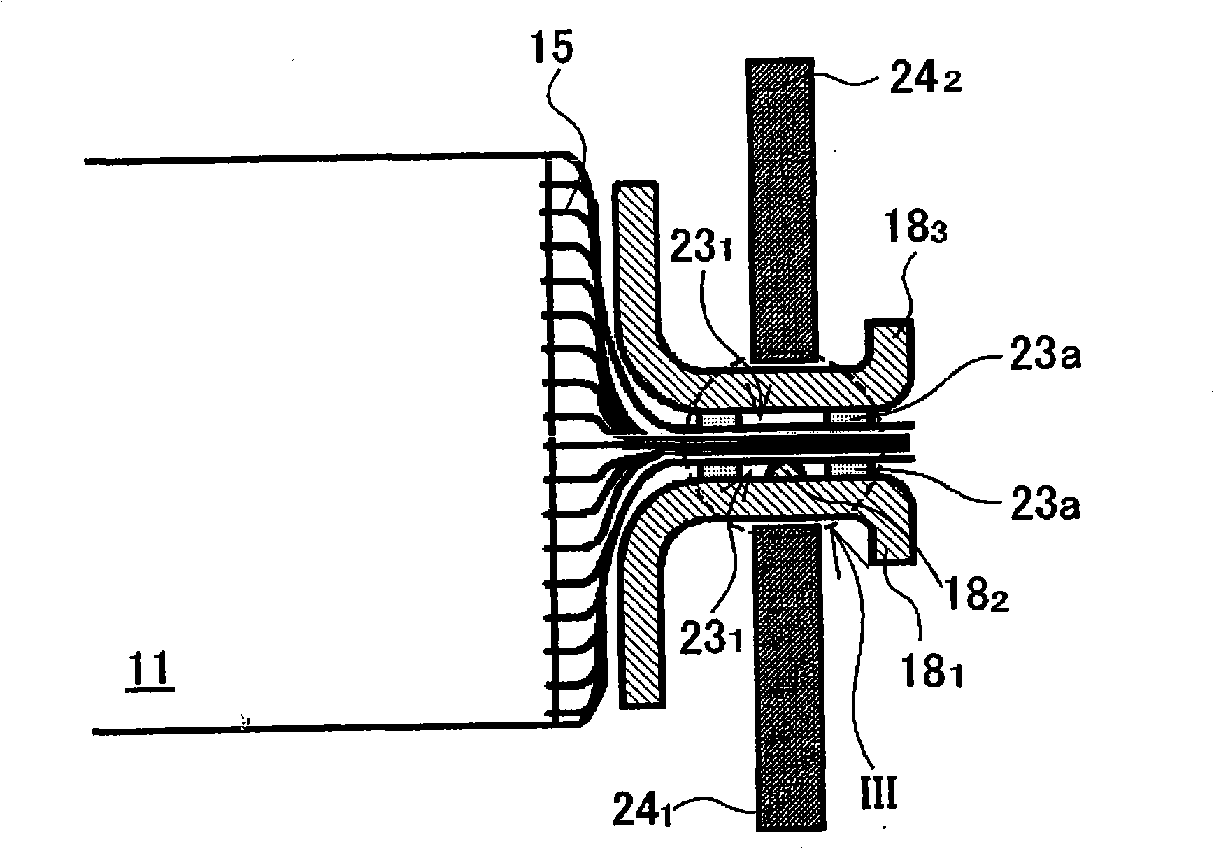
[0098] In the prismatic nonaqueous electrolyte secondary battery 10 of Example 1, as shown figure 2 and image 3 As shown, as the negative electrode current collector 18 1 , using a protrusion 18 formed in the central part 2 The current collector, the opening 23 is formed in the central part of the heat-welding resin tape 23a 1 while using and resistance welding examples. However, if especially continuous resistance welding, the electrode rod 24 1 and 24 2 Since it becomes hot, the heat-welding resin tape 23a itself may soften before electric current flows during resistance welding. If resistance welding is performed in such a state, during resistance welding, the electrode rod 24 is used from both sides. 1 and 24 2 Press negative electrode current collector 18 1 and negative electrode current collector supporting member 18 3 , meanwhile, resistance welding is performed, so, as Figure 5 As shown, the heat-welding resin tape 23a itself may protrude toward the welded...
Embodiment 3
[0104] In Example 1 and Example 2, an example was shown in which the heat-welding resin tape 23a was used as the insulating sealing material, but an insulating tape with a paste material may also be used. use Figure 8 ~ Figure 10 , the structure of the resistance welded part of the rectangular battery of Example 3 using the insulating tape 23b with the paste material as the insulating sealing material will be described. Also, in Figure 8 ~ Figure 10 in, with Figure 6 and Figure 7 The same reference numerals are assigned to the same components in the shown configurations, and detailed description thereof will be omitted.
[0105] The structure of the resistance welded part of Example 3 is different from that of the resistance welded part of Example 2 as follows. That is, in Example 2, the heat-welding resin tape 23a is used as the insulating sealing material. In contrast, Only the point that the insulating tape 23b with a paste material is used in Embodiment 3, other st...
PUM
| Property | Measurement | Unit |
|---|---|---|
| Thickness | aaaaa | aaaaa |
Abstract
Description
Claims
Application Information