Anode material for super capacitor battery and preparing method thereof

A positive electrode material and supercapacitor technology, applied in the direction of electrode manufacturing, battery electrodes, capacitors, etc., can solve the problems that the high current discharge performance cannot meet the needs of electric tools, and can not be used alone as a vehicle power supply, etc., to achieve an easy-to-control effect

Inactive Publication Date: 2008-12-31
CENT SOUTH UNIV
View PDF1 Cites 24 Cited by
  • Summary
  • Abstract
  • Description
  • Claims
  • Application Information

AI Technical Summary

Problems solved by technology

[0002] Lithium-ion power battery is gradually becoming mature, it has high energy density, but its high-current discharge performance still cannot meet the needs of electric tools
The power density of a

Method used


Image

  • Anode material for super capacitor battery and preparing method thereof
  • Anode material for super capacitor battery and preparing method thereof
  • Anode material for super capacitor battery and preparing method thereof

Examples


Embodiment 1

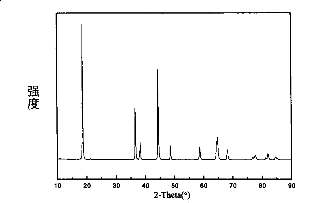
[0016] Nanoscale LiCoO 2 Put it into mechanical fusion equipment, carry out mechanical fusion granulation, and form uniform spherical particles with a size of about 10 microns; then add 10% of its weight of activated carbon, and then perform mechanical fusion treatment. The XRD of the obtained composite material is shown in figure 1 , see SEM figure 2 . With the material as the positive electrode and the metal lithium sheet as the negative electrode, LiPF 6 / EC+DEC is assembled into a battery with electrolyte solution, and its discharge capacity is tested. The discharge specific capacities of 0.5C and 10C are 95mAh / g and 85mAh / g, respectively.

Embodiment 2

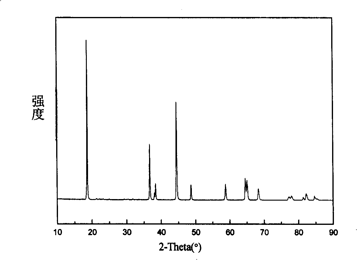
[0018] Nano-LiNi 1 / 3 mn 1 / 3 co 1 / 3 o 2 Put it into mechanical fusion equipment, carry out mechanical fusion granulation, and form spherical particles with a size of about 8 microns; then add 50% of its weight of mesoporous carbon, and then perform mechanical fusion. The XRD of the obtained composite material is shown in image 3 , see SEM Figure 4 . With the material as the positive electrode and the metal lithium sheet as the negative electrode, LiPF 6 / EC+DEC is an electrolyte assembled into a battery, and its first charge and discharge curve is shown in Figure 5 , the discharge specific capacities of 0.5C and 10C are 102mAh / g and 88mAh / g, respectively.

Embodiment 3

[0020] Nano LiFePO 4 Put it into mechanical fusion equipment, carry out mechanical fusion granulation, and form spherical particles with a uniform size of about 5 microns; then add carbon fiber with 100% weight of lithium iron phosphate, and then perform mechanical fusion treatment to obtain a composite material, which is used as the positive electrode , metal lithium sheet as negative electrode, LiPF 6 / EC+DEC is an electrolyte assembled into a battery, and its second charge and discharge curve is shown in Figure 6 , for rate performance see Figure 7 , the discharge specific capacities of 0.5C, 5C and 10C are 101mAh / g, 96mAh / g and 92mAh / g, respectively. Cycle performance (10C) see Figure 8 , The capacity retention rate was 97% after 50 cycles.


PUM

PropertyMeasurementUnit
Discharge specific capacityaaaaaaaaaa

Abstract

The invention discloses a super capacitor-battery used anode material and a preparation method thereof. Mechanical fusion granulation is carried out on compound material power which has the property of de-lithium-intercalation to obtain ball grains of 1 to 15 micro; porous carbon material with the weight percentage of 10 percent to 100 percent of the weight of the de-lithium-intercalation compound material is added and then the mechanical fusion granulation is carried out, thereby obtaining de-lithium-intercalation compound material coated with porous carbon material. The method of the invention has simple process, and the material obtained has both the large capacity property of a battery material and the high power of a capacitor material. The storage capacity of the anode material can reach 100mAh/g, and the discharge capacity of 10C can reach 90 percent of the discharge capacity of 0.5C. The anode material is the potential electrode material of the novel energy storage system which is applied to an electric driving automobile.

Description

technical field [0001] The invention relates to the field of electrode materials for electrochemical energy storage systems, in particular to positive electrode materials for supercapacitor-batteries. Background technique [0002] Lithium-ion power batteries are gradually becoming mature. They have high energy density, but their high-current discharge performance still cannot meet the needs of electric tools. The power density of a supercapacitor is dozens or even hundreds of times that of an ordinary battery, but its energy density is only 1 / 10 of that of a lithium-ion battery, and it cannot be used alone as a vehicle power supply. [0003] Therefore, it has been proposed to combine lithium-ion batteries and supercapacitors, that is, supercapacitor-battery systems. At present, the main combination method is an "external combination", that is, the two monomers are combined into an energy storage system through the power management system, and one of the monomers is allowed ...

Claims


Application Information

Patent Timeline
IPC IPC(8): H01M4/58H01M4/48H01M4/04B22F1/00H01G9/042H01M16/00H01M4/62
CPCY02E60/10Y02E60/13
Inventor 胡国荣杜柯彭忠东李劼曾涛
Owner CENT SOUTH UNIV
Why Eureka
Try Eureka