Vehicle braking kinetic-energy regeneration device

A vehicle brake and regeneration device technology, which is applied in the direction of power devices, air pressure power devices, vehicle components, etc., can solve the problems of poor practical applicability and poor energy saving effect, so as to improve fuel economy, prolong service life, The effect of not being easily polluted

Inactive Publication Date: 2009-01-07
HARBIN INST OF TECH
View PDF0 Cites 46 Cited by
  • Summary
  • Abstract
  • Description
  • Claims
  • Application Information

AI Technical Summary

Problems solved by technology

[0003] The purpose of the present invention is to provide a vehicle braking kinetic energy regeneration device to solve the prob

Method used


Image

  • Vehicle braking kinetic-energy regeneration device

Examples


specific Embodiment approach 1

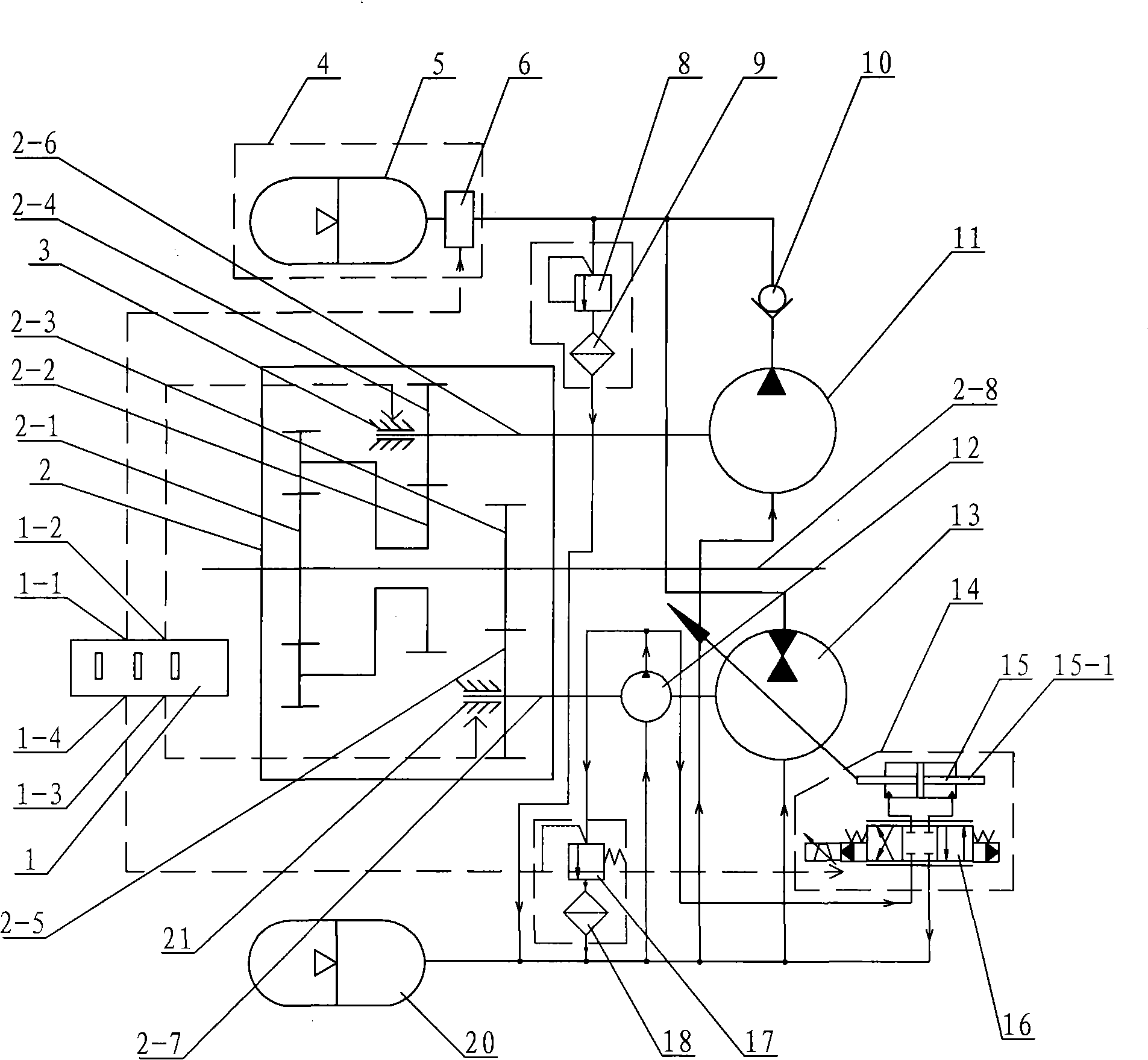
[0007] Specific implementation mode one: combine figure 1 Describe this embodiment, this embodiment consists of a central controller 1, a planetary gear mechanism 2, a first brake 3, an accumulator assembly 4, a high-pressure hydraulic accumulator 5, a two-way electro-hydraulic reversing valve 6, a first relief valve 8. First filter 9, one-way valve 10, charge pump 11, control oil circuit hydraulic pump 12, hydraulic pump motor 13, hydraulic pump motor control assembly 14, second relief valve 17, second filter 18, low pressure The hydraulic accumulator 20 and the second brake 21 are made up, and the planetary gear mechanism 2 is made up of the first driving wheel 2-1, the second driving wheel 2-2, the third driving wheel 2-3, the first driven wheel 2-4, the second driving wheel Two driven wheels 2-5, the first driven shaft 2-6, the second driven shaft 2-7 and the driving shaft 2-8 are composed of the first driving wheel 2-1, the second driving wheel 2-2 and the third driving w...

specific Embodiment approach 2

[0008] Specific implementation mode two: combination figure 1 Describe this embodiment, the hydraulic pump motor control assembly 14 of this embodiment is composed of a variable oil cylinder 15 and an electro-hydraulic servo valve 16, the oil inlet port of the electro-hydraulic servo valve 16 is connected with the oil outlet port of the hydraulic pump 12 in the control oil circuit, The oil outlet port of the electro-hydraulic servo valve 16 is connected with the oil inlet port of the variable oil cylinder 15, the oil inlet port of the electro-hydraulic servo valve 16 is connected with the oil outlet port of the variable oil cylinder 15, and the piston rod 15-1 in the variable oil cylinder 15 is connected with the hydraulic pump motor 13 connections.

[0009] Working principle: The planetary gear mechanism 2 is installed between the engine and the transmission of the vehicle, the braking system of the original vehicle is retained, and the drive shaft of the original vehicle is ...


PUM


Abstract

A vehicle braking kinetic-energy regenerative device relates to a petrol-saving attachment for reclaiming the vehicle braking kinetic-energy, and aims to solve the problem of poor energy-saving effect in the prior vehicle braking kinetic-energy regenerative device. In the vehicle braking kinetic-energy regenerative device, a first brake and a slippage pump are respectively arranged at two ends of a first driven shaft; a second brake and a hydraulic pump motor are respectively arranged at two ends of a second driven shaft; a control oil-channel hydraulic pump is arranged at the middle part of the second driven shaft; an electrohydraulic change valve is connected with a high-pressure hydraulic accumulator; and a central control unit is respectively connected with the brakes, the second brake, the hydraulic pump motor and the electrohydraulic change valve. The vehicle braking kinetic-energy regenerative device recycles the vehicle braking kinetic-energy when the vehicle brakes, and drives the vehicle by releasing the recycled energy when the vehicle starts. The work efficiency of the energy is improved by the active stamping of the slippage pump. The vehicle braking kinetic-energy regenerative device is applicable to city buses and engineering vehicles, and can improve the kinetic performance and the braking performance of vehicles only by slightly reforming the prior vehicles.

Description

technical field [0001] The invention relates to a fuel-saving additional device for recovering braking kinetic energy of a vehicle, which can be used in various urban public transport vehicles and engineering vehicles to recover and reuse the braking kinetic energy of the vehicle, and can automatically adjust the fuel-saving device for operating conditions of the engine. Background technique [0002] As the number of vehicles increases year by year, the energy consumption and exhaust emissions of urban buses, which start and brake frequently, are becoming more and more serious, which has caused huge pressure on my country's energy security and environmental protection. Traditional automobiles use the frictional resistance generated by the mechanical braking system to achieve deceleration or parking, and the braking kinetic energy of the vehicle is converted into heat and wasted in vain. Existing vehicle braking kinetic energy recovery adopts fuel-saving booster device, altho...

Claims


Application Information

Patent Timeline
IPC IPC(8): B60K6/12
CPCY02T10/6208Y02T10/62
Inventor 姜继海孙辉苏文海王昕
Owner HARBIN INST OF TECH
Why Eureka
Try Eureka