Tube-type electric motor manual, electric clutch controller

A technology of electric clutch and tubular motor, which is applied in the direction of clutches, mechanical equipment, door/window protection devices, etc. It can solve the problems of unsuitable, large, and laborious opening and closing of the door, and achieves reduced resistance, fewer parts, and better pulling flexible effects

Active Publication Date: 2009-01-07
孙宜培
View PDF2 Cites 7 Cited by
  • Summary
  • Abstract
  • Description
  • Claims
  • Application Information

AI Technical Summary

Problems solved by technology

A clutch mechanism with a slider and a spur gear is used instead of a clutch mechanism composed of a worm wheel and a worm. There is a spring on the slider to adjust the lateral movement distance of the slider, that is, to adjust the meshing depth of the spur teeth on the slider and the spur gear. Ensure that there is no gap when the rolling door is pulled to the end, and all the parts of the control switch are installed in the inner and outer end covers, so as not to be polluted and affected by the surrounding environment, but the above two patents are more suitable for controlling the smaller rolling door with a weight of less than 100 kg It is used on the sheet, and it is very laborious to open and close the door sheet, requiring a lot of strength, and it is not suitable for use on large rolling doors and windows.

Method used


Image

  • Tube-type electric motor manual, electric clutch controller
  • Tube-type electric motor manual, electric clutch controller
  • Tube-type electric motor manual, electric clutch controller

Examples


Embodiment Construction

[0015] Embodiments of the present invention will be further described below in conjunction with the accompanying drawings.

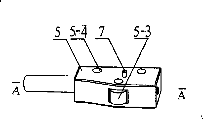
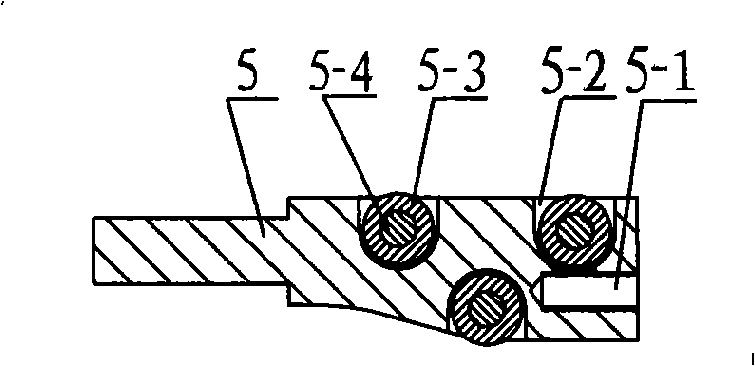
[0016] One end of slide block 5 is cylindrical, and one end is elongated, and the lower end surface of elongated shape has inclined-plane, and on inclined-surface and corresponding upper end surface, there are one or more blind holes that do not communicate, or triangular distribution of three holes. Blind hole 5-2, connects rotatable pulley 5-3 with rivet 5-4 in blind hole, and screw hole 5-1 is arranged on the outer end face of strip shape, is used for fixing the pull bar 10 that has spring 12 rope 11, There is a raised small sliding column 7 in the middle of the strip-shaped upper end face, such as figure 2 , image 3 shown.

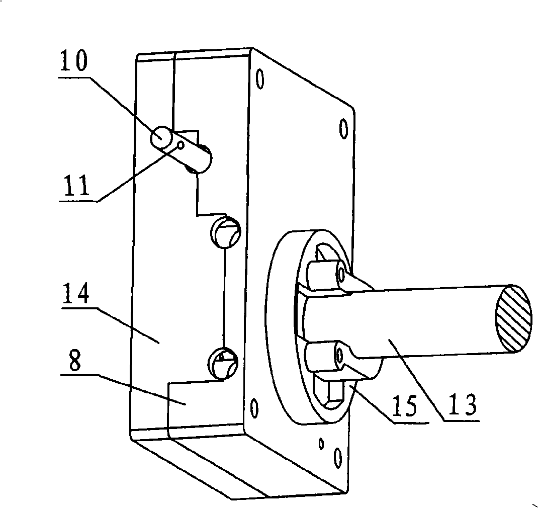
[0017] One end of the torsion spring 3 is fixed on the convex column on the lower surface of the arc rack 4, the torsion spring 3 and the arc rack 4 are set on the rotating shaft 2 on the inner end cover 8, and the other end ...


PUM


Abstract

The present invention relates to a tubular motor manual electric clutch controller. An arc rack is matched with a spur gear at a rotating rod and a pulley at a slide rod. A smaller traveler at the slide rod is matched with a slide way buckle which is connected with an external end cover. The slide rod is equipped with one or more than one pulley and is connected with a pull rod with a spring. The arc rack is connected with a rotating shaft which is provided with a torsional spring. The rotating shaft is fixed on an internal end cover. The original slide rod is decomposed into two independently moving parts of the slide rod and the arc rack to reduce the spring. The slide rod is provided with a bevel and is equipped with the pulley. The movement of the slide rod is changed into the sliding of the pulley. The pulley can be departed from or pressed on the arc rack just by very short distance of the movement of the pull rod. The arc rack rotates for certain degrees along the rotating shaft and can be departed from or be meshed with the spur gear. The tubular motor manual electric clutch controller can achieve the great just by few pull. The tubular motor manual electric clutch controller is a manually operated controller saving most labor at the prior market and has simple and compact structure and low cost. The tubular motor manual electric clutch controller can be installed at rolling doors with different specifications and sizes and has fast pulling speed and high efficiency.

Description

technical field [0001] The invention relates to a controller used in conjunction with a tubular motor clutch, which is especially suitable for use in places where there are frequent power outages. When a power failure occurs, the clutch must first be disengaged from the electric transmission part of the tubular motor so as to manually open and close rolling doors and windows. Tubular motor manual, electric clutch controller. Background technique [0002] Patent No. CN200610050535.5 "tubular motor clutch switch" provides a cable and one end of the torsion spring fixed on the rotating piece, the rotating piece is fixed on the worm, the pull rod on the rotating piece cooperates with the chute with positioning block, the chute Connected to the outer end cover, the pull cable directly controls the rotating piece to rotate 90°, and drives the worm integrated with it to rotate 90° synchronously, so that the worm and the worm wheel can be disengaged or reset. This switch adopts a c...

Claims


Application Information

Patent Timeline
Patent Type & Authority Applications(China)
IPC IPC(8): E06B9/74F16D48/00
Inventor 俞锡鹏孙宜培
Owner 孙宜培
Why Eureka
Try Eureka