Method for removal of unburned carbon in fly ash

一种未燃碳、飞灰的技术,应用在化学仪器和方法、固体废物的清除、具有旋转搅拌装置的混合机等方向,能够解决堵塞飞灰供给管、不能充分混合等问题,达到设置面积减少、持续稳定设备成本、经济性优异的效果

Inactive Publication Date: 2009-01-07
MITSUI ENG & SHIPBUILDING CO LTD
View PDF1 Cites 5 Cited by
  • Summary
  • Abstract
  • Description
  • Claims
  • Application Information

AI Technical Summary

Problems solved by technology

[0008] Specifically, there is the following problem: in the mixing tank 62 shown in FIG. 9, if fly ash 87 and water 88 are to be stirred to generate slurry 89, fly ash 87 will adhere around the rotating shaft 81 of the stirring blade 82 and cannot In addition, the water or water vapor in the mixing tank 52 wets the fly ash 87 and blocks the fly ash supply pipe 84

Method used


Image

  • Method for removal of unburned carbon in fly ash
  • Method for removal of unburned carbon in fly ash
  • Method for removal of unburned carbon in fly ash

Examples


Embodiment Construction

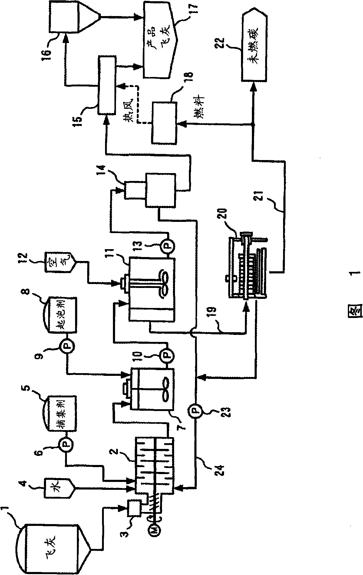
[0029] An embodiment of the present invention will be described based on FIG. 1 . Fig. 1 shows a system diagram of an equipment system for practicing the present invention.

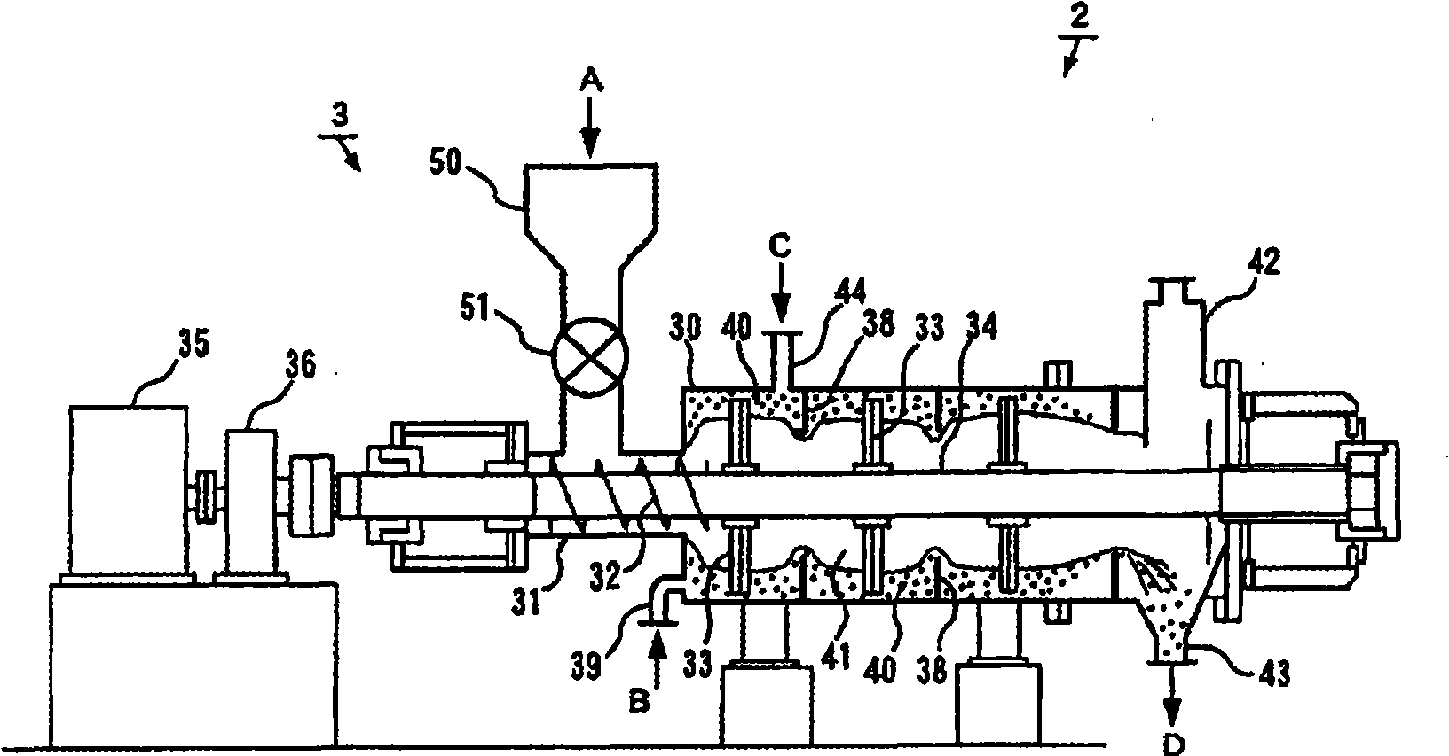
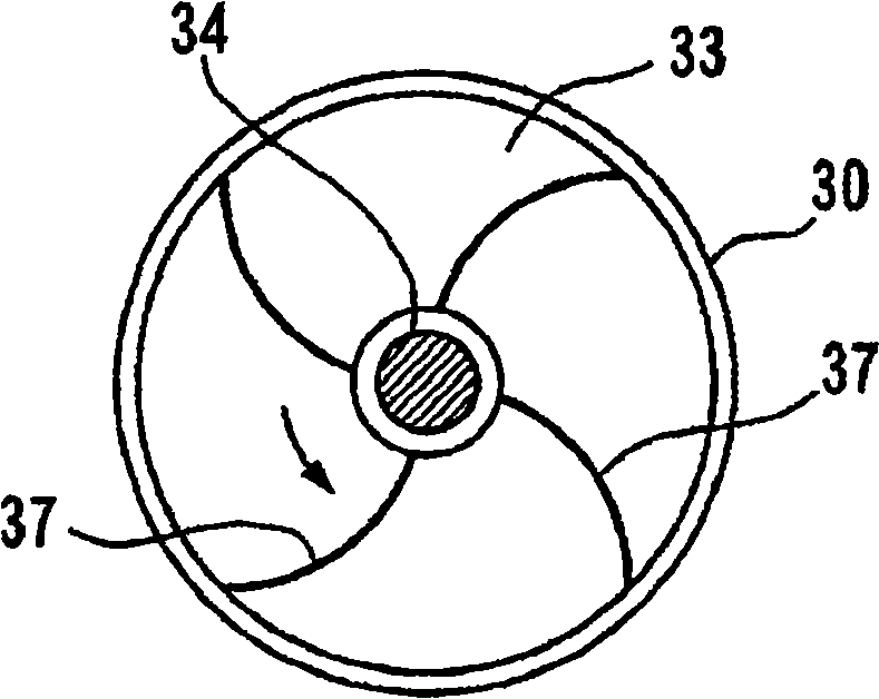
[0030] This system is mainly produced by adding a collector to the hybrid mixer (hybrid mixer) 2 that imparts high shear force while preparing a slurry containing fly ash and water, and adding a foaming agent to the slurry produced by the above-mentioned hybrid mixer 2 Air bubbles, a flotation machine 11 for attaching and floating unburned carbon in the fly ash for separation, a solid-liquid separator 14 for separating and recovering the fly ash from the sediment separated by the above-mentioned flotation machine 11, and the same A dehydrator 20 is configured to dehydrate the floating matter separated by the above-mentioned flotation machine 11 and recover unburned carbon.

[0031] The devices constituting the system will be specifically described below.

[0032] The fly ash tank 1 is used to store and ...


PUM


Abstract

The object is to remove unburned carbon in a fly ash in a stable and economically advantageous manner. A fly ash, water and a trapping agent are mixed together in a hybrid mixer (2), a shearing force is applied to the mixture to prepare a slurry containing surface-modified unburned carbon within a short time, a foaming agent is added to the slurry, and then the unburned carbon is separated by performing flotation separation in a flotator (11).

Description

technical field [0001] The present invention relates to a method for removing unburned carbon in fly ash, and particularly relates to a method for removing unburned carbon contained in fly ash discharged from coal-fired power plants and the like. Background technique [0002] Coal can be used stably over a long period of time as an energy source with confirmed recoverable reserves of more than 200 years. Therefore, the proportion of coal thermal power generation is increasing year by year, and the production of coal ash (hereinafter referred to as "fly ash") is expected to further increase in the future. [0003] Under such circumstances, it is necessary to effectively utilize fly ash in large quantities from the viewpoint of environmental protection and effective utilization of resources. [0004] At present, fly ash is used as a cement admixture after removing unburned carbon. By improving the removal rate of this unburned carbon and improving the quality of fly ash, its u...

Claims


Application Information

Patent Timeline
Patent Type & Authority Applications(China)
IPC IPC(8): B03D1/02B01F7/02B01F15/02B03B1/00B09B3/00B09B5/00C04B18/08
CPCB01F7/048B03D1/02B01F15/0251B01F3/1221C04B18/08Y10S106/01Y02W30/91B01F23/53B01F27/707B01F35/71775C04B20/023B09B5/00B01F27/60B01F35/71
Inventor 阿部一雄铃木隆男小山斋松尾和芳斋藤绅一郎
Owner MITSUI ENG & SHIPBUILDING CO LTD
Why Eureka
Try Eureka