Radial rolling bearing, in particular single-row spherical-roller bearing

一种球面滚子、滚动轴承的技术,应用在径向滚动轴承领域,能够解决刮擦、轴承轴向和径向承载能力小等问题,达到减小轴向结构空间、径向和轴向承载能力高、高轴向承载能力的效果

Inactive Publication Date: 2009-01-14
SCHAEFFLER KG
View PDF3 Cites 7 Cited by
  • Summary
  • Abstract
  • Description
  • Claims
  • Application Information

AI Technical Summary

Problems solved by technology

[0007] Although it is achieved by making such a spherical roller bearing, the spherical roller is similar to the deep groove ball bearing The ball has a large contact surface with its raceway in the bearing ring, and the bearing can be equipped with a larger number than ordinary single row deep groove ball bearings However, in view of the number of rolling elements, compared with the number of rolling elements that can be increased by the axial assembly method, the eccentric assembly method will definitely cause scratches
Therefore, although the axial structural space and weight of the bearing can be reduced and its axial load-bearing capacity can be improved compared with ordinary deep groove ball bearings, the improvement of the axial and radial load-bearing capacity of the bearing is relatively small.

Method used


Image

  • Radial rolling bearing, in particular single-row spherical-roller bearing
  • Radial rolling bearing, in particular single-row spherical-roller bearing
  • Radial rolling bearing, in particular single-row spherical-roller bearing

Examples


Embodiment Construction

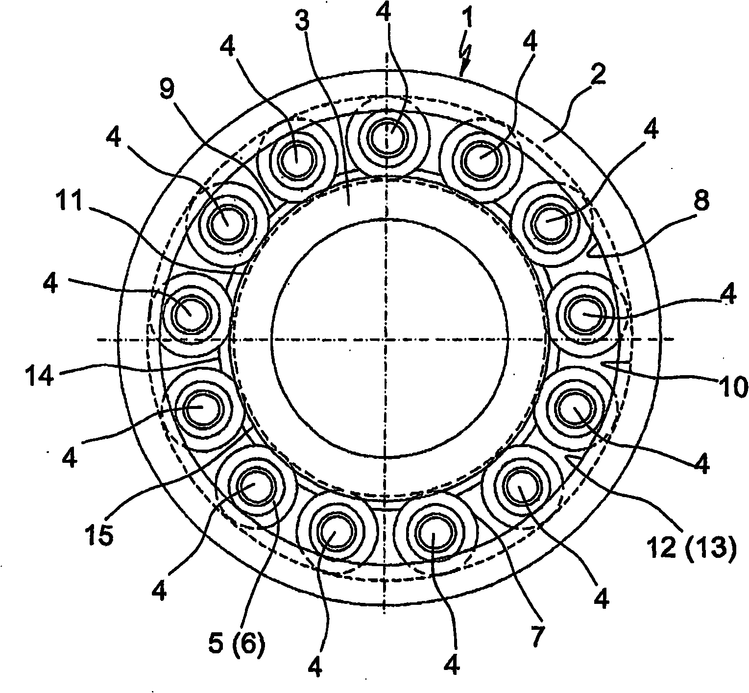
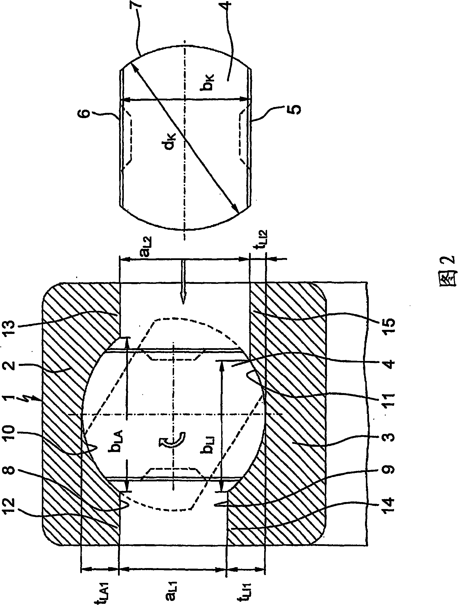
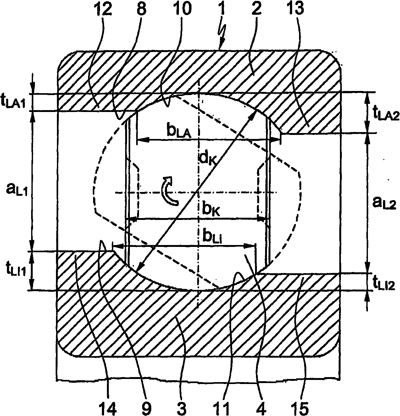
[0020] Depend on figure 1It can be clearly seen that the radial rolling bearing 1 designed as a single row spherical roller bearing is mainly composed of a bearing outer ring 2, a bearing inner ring 3 and many spherical rollers 4 arranged between the bearing rings 2 and 3, such as It can be seen in FIG. 2 that the spherical rollers each have two sides 5 , 6 that are symmetrically flattened from the spherical basic shape and are arranged parallel to one another and are kept at a uniform distance from one another in the circumferential direction by a bearing cage (not shown). These spherical rollers 4, as can also be clearly seen in FIG. 2, have a diameter d between their sides 5, 6 of their spherical basic shape k about 70% of the width of b k , and use its rolling surface 7 to roll in two grooved raceways 10, 11 processed on the inner side 8 of the bearing outer ring 2 and the outer side 9 of the bearing inner ring 3. These raceways respectively pass through two axial Edges ...


PUM


Abstract

The invention relates to a radial rolling bearing, in particular single-row spherical-roller bearing, which is composed substantially of an outer bearing ring (2) and an inner bearing ring (3) and of a plurality of spherical rollers (4), which spherical rollers (4) are arranged between said bearing rings (2,3), which spherical rollers (4) have in each case two side faces (5,6) which are flattened symmetrically from a spherical basic shape and are arranged parallel to one another, and which spherical rollers (4) are retained with uniform spacing to one another in the peripheral direction by means of a bearing cage. Here, the spherical rollers (4) have a width (bk) between their side faces (5,6) of approximately 70% of the diameter (dk) of their spherical basic shape, and roll with their running faces (7) in two groove-shaped raceways (10,11) which are formed in the inner side (8) of the outer bearing ring (2) and in the outer side (9) of the inner bearing ring (3). According to the invention, at least one of the axial rims (12, 13, 14, 15) which delimit the groove-shaped raceways (10,11) in the bearing rings (2,3) is designed to be reduced in radial height such that the radial bearing (1) can, by means of the increased spacing (aL2) of said rim (12, 13, 14, 15) to the radially opposite rim (12, 13, 14, 15), be equipped with an increased number of spherical rollers (4) in an axial assembly process.

Description

technical field [0001] The invention relates to a radial rolling bearing according to the features of the preamble of claim 1, which can be realized particularly advantageously on single-row spherical roller bearings, which are used, for example, as fixed bearings for drive and output shafts of motor vehicle gearboxes. Background technique [0002] Professionals in rolling bearing technology generally know that single row deep groove ball bearings are rigid, non-removable radial rolling bearings, which are mainly characterized by their high radial and axial load carrying capacity and, due to their low friction, they have all The highest speed limit among all types of bearings. These deep groove ball bearings have been known for a long time and consist essentially of an outer bearing ring and an inner bearing ring and a large number of balls arranged between the bearing rings as rolling elements. The inner side of the outer ring and the outer side of the inner ring are respe...

Claims


Application Information

Patent Timeline
Patent Type & Authority Applications(China)
IPC IPC(8): F16C19/34F16C43/06
CPCF16C19/26F16C33/36F16C2240/40F16C43/06F16C19/08F16C33/46F16C35/06
Inventor H·霍夫曼H·多普林G·戈佩尔特
Owner SCHAEFFLER KG
Why Eureka
Try Eureka