Blower fan and washing and drying integrated machine

A fan and the technology of the fan, applied in the field of the fan and the integrated washing and drying machine with the fan, can solve the problems of large wind pressure loss, low drying efficiency, and less air circulation times of the washing drum in the dehumidification and drying system, and achieve low cost , easy processing, the effect of reducing the thickness

Active Publication Date: 2009-01-21
QINGDAO HAIER DRUM WASHING MACHINE
View PDF0 Cites 5 Cited by
  • Summary
  • Abstract
  • Description
  • Claims
  • Application Information

AI Technical Summary

Problems solved by technology

[0006] The invention provides a fan and an integrated washing and drying machine, which can solve the problems of large wind pressure loss in the dehumidification and drying system of the washing and drying integrated machine in the prior art, less air circulation times in the washing tub, and low drying efficiency

Method used


Image

  • Blower fan and washing and drying integrated machine
  • Blower fan and washing and drying integrated machine
  • Blower fan and washing and drying integrated machine

Examples


Embodiment 1

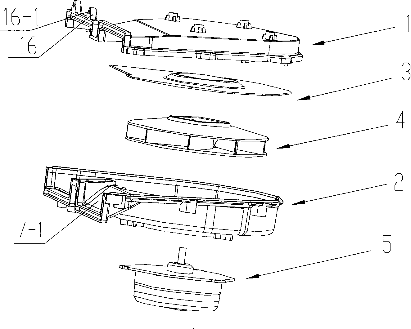
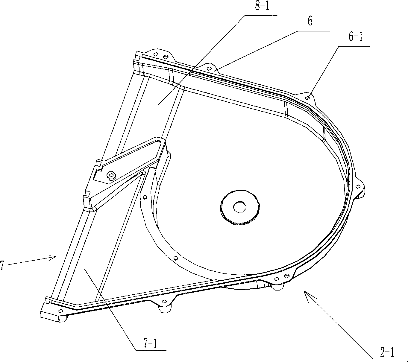
[0034] Embodiment one, such as Figure 2-6 As shown, the present invention proposes a fan, which includes an upper cover 1 and a volute 2, the upper cover 1 and the volute 2 have a part of the frame of the inlet 7 and the air outlet 8 adjacent to each other, the upper cover 1 and the volute A turning air channel is formed between the top surfaces 3 of the casing, and the inlet 7 of the turning air channel is adjacently arranged on one side of the air outlet 8, that is, after the upper cover 1 is fastened to the volute 2, an inlet on the same side of the volute is formed 7 and the air outlet 8, the frames of the inlet 7 and the air outlet 8 in this embodiment are square and located on the same plane, the actual positional relationship can be determined according to the needs. Installing lugs 16 are provided around the frame of the inlet 7 and the air outlet 8, and the mounting lugs 16 have screw holes 16-1 for connecting with other components. , There is a bolt hole 6-1 on the...

Embodiment 2

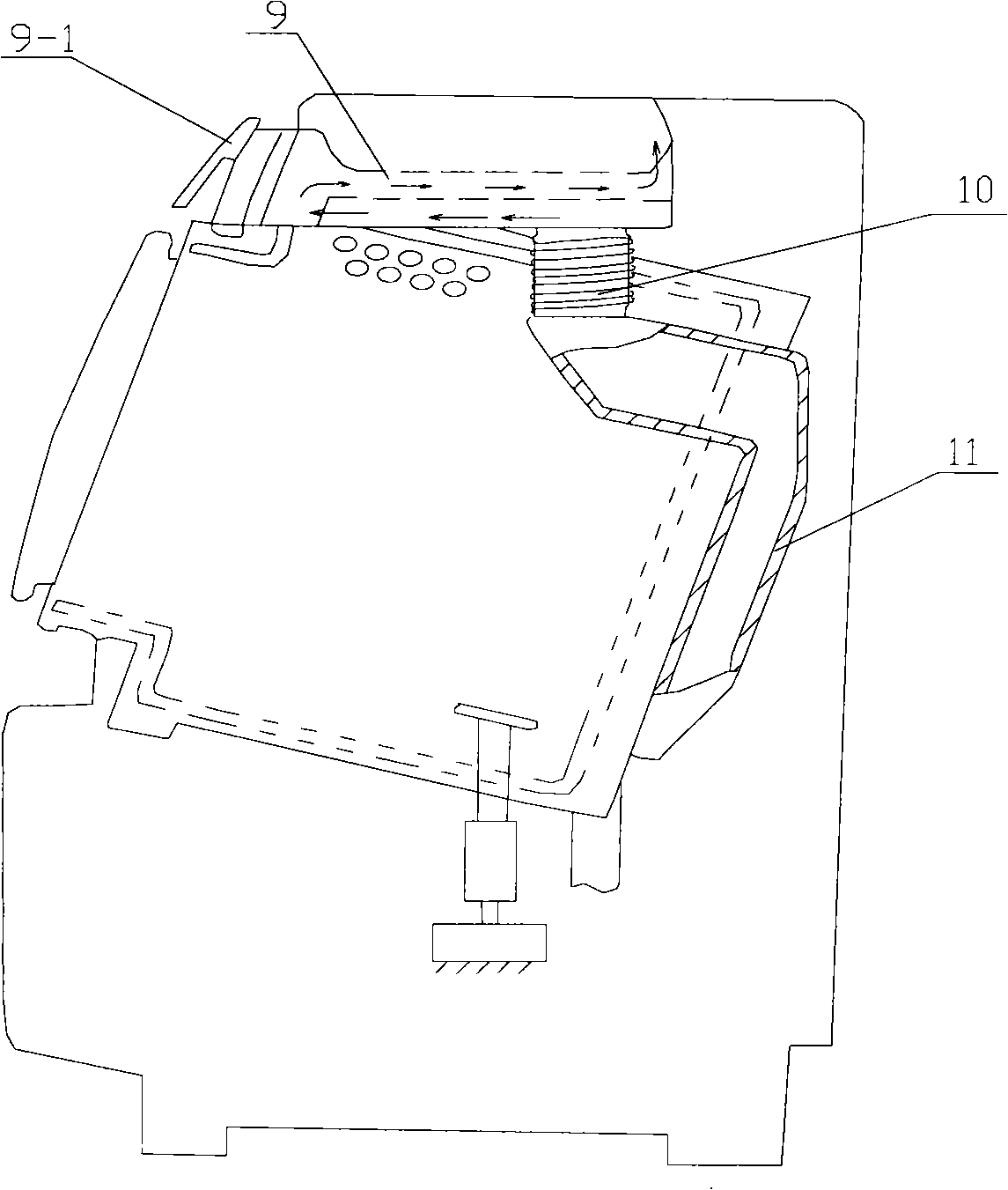
[0039]Embodiment two, such as Figure 7 and Figure 8 As shown, the present invention further proposes an all-in-one washing and drying machine with the fan described in Embodiment 1, including a condenser 11 and a lint filter, and the lint filter is located in the lint filter housing 9-2, so Figure 7 Not shown in the figure, the lint filter housing 9-2 is connected with the inlet 7 of the fan by bolts, the air outlet 8 of the fan is connected with the heat exchanger 12, and the airflow sucked from the inlet 13 is dehumidified by the condenser 11, and the airflow flows smoothly. as Figure 7 The arrow shown enters the lint filter. Since the lint filter housing 9-2 is a straight sleeve and is directly connected to the fan inlet 7, the airflow blown from the lint filter directly enters the inlet 7. The airflow blown in by the inlet 7 follows the upper slope 7-1 to the top of the volute top surface 3 and turns to the air duct, then enters the fan 4 from the air inlet 3-2 in th...


PUM


Abstract

The invention discloses a fan and a washing and drying integral machine, which can resolve problems that in the prior art, a dehumidifying and drying system of a washing and drying integral machine has high wind pressure loss, few air circulating times in a washing cylinder and low drying efficiency. The technical scheme is that an upper cover is arranged above a spiral casing, a turning wind passage is formed between the upper cover and the top face of the spiral casing, the inlet of the turning wind passage is adjacently arranged on one side of a wind outlet, a washing filter casing which is a straight sleeve is directly butted with a wind inlet, thereby guiding the original wind inlet to the adjacent side of the wind outlet via the turning wind passage according to adjusting wind passages, enabling wind blowing from the washing filter casing to directly enter the inlet to enter the fan via the wind inlet of the spiral casing, enabling air flow to be capable of smoothly passing through the wind passage, reducing wind pressure loss, increasing air circulating times in the washing cylinder in unit time, and further increasing drying efficiency.

Description

technical field [0001] The invention belongs to the technical field of washing and drying integrated machines, and relates to an improvement of a dehumidification and drying system, in particular to a fan and an integrated washing and drying machine with the fan. Background technique [0002] The dehumidification and drying system in the washer-dryer removes moisture from wet clothes by sucking in hot air generated by a heater. At present, all-in-one washing and drying machines mostly use water-cooled heat exchangers such as figure 1 As shown, the humid air in the washing drum is sucked out by the fan, and as shown by the arrow in the figure, it passes through the condenser 11 and the hose 10 to reach the front of the machine, and after passing through the lint filter 9, it enters from the inlet above the volute. The tuyere enters the fan volute, and the air blown from the volute outlet is heated by the heat exchanger, and then directly blows into the washing tub, and thus ...

Claims


Application Information

Patent Timeline
Patent Type & Authority Applications(China)
IPC IPC(8): F04D29/44D06F58/20D06F58/22D06F25/00
Inventor 迟宗锐张帅姜文峰侯永顺沈伟华王坚
Owner QINGDAO HAIER DRUM WASHING MACHINE
Why Eureka
Try Eureka