
Method for positioning multi-input multi-output radar system target

A target positioning and radar system technology, applied in radio wave measurement systems, radio wave reflection/re-radiation, utilization of re-radiation, etc. The effect of accuracy, enhanced detection and localization capabilities

Inactive Publication Date: 2009-01-21
XIDIAN UNIV
View PDF0 Cites 34 Cited by
  • Summary
  • Abstract
  • Description
  • Claims
  • Application Information

AI Technical Summary

Problems solved by technology

The reason is that there are errors in the direction estimation due to reasons such as the array manifold, which leads to inaccurate coefficient matrices, and the least squares algorithm is based on the accurate known coefficient matrix, so the least squares method is no longer optimal from a statistical point of view. , it will be biased, and the covariance of the bias will increase due to the effect of the error of the coefficient matrix
Although the total least squares is only very effective under the condition that the coefficient error matrix is ​​uncorrelated and has the same variance, in target positioning, this condition does not exist, so the target position cannot be accurately positioned

Method used


Image

  • Method for positioning multi-input multi-output radar system target
  • Method for positioning multi-input multi-output radar system target
  • Method for positioning multi-input multi-output radar system target

Examples


Embodiment Construction

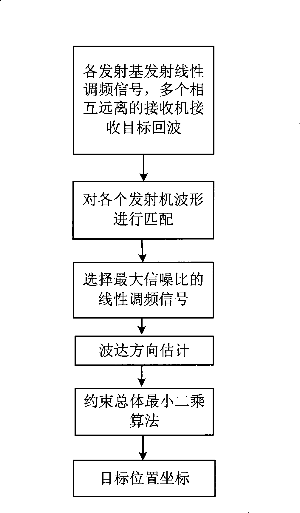
[0015] refer to figure 1 , the target detection of the present invention is carried out as follows:

[0016] Step 1: Transmit FM signal and receive target echo signal.

[0017] M transmitters transmit a chirp signal f i (t), i=1, . . . , M, where t is a time variable, and these M signals are mutually orthogonal. f i (t) After being reflected by the target, it is received by the jth receiver, with σ ij f i (t) means, where, σ ij is the quantity related to target reflection and path loss, j=1,...,N. When M transmitted signals are reflected, the signal received by the jth receiver is s ij ( t ) = Σ i = 1 M σ ij f i ( t ) + n j ...


PUM


Abstract

The invention discloses a target location method for MIMO radar (multi input multi output), for resolving the low accuracy problem of the prior MIMO radar which locates target via least square method. The invention utilizes the error correlation character of the coefficient matrix and utilizes constraint total least square method to realize target location. The method comprises the steps of emitting orthogonal signals for each transmitter distanced with each other enough, at the receiver, using the orthogonality of the emitted signals and a match filter method to separate the echo signals of emission array elements; using each receiver to measure the direction of the target echo to attain the object angle; using the constraint total least square method to realize the accurate location of the target. The invention has the advantages of high location accuracy and can locate air target in tracking and guidance.

Description

technical field [0001] The invention relates to the field of radar technology, in particular to the application of a multiple-input multiple-output radar system, and in particular to a target positioning method for a multiple-input multiple-output radar system. Background technique [0002] The emergence of current stealth aircraft has made the traditional single-engine and single-receive radar a great challenge. Due to the shape design of stealth aircraft, most of the electromagnetic waves irradiated on it are reflected to other directions, so a multiple-input multiple-output MIMO radar system emerged as the times require, and has become a current research hotspot. Different from the coherent waveforms transmitted by traditional phased array radars, MIMO radars transmit orthogonal or correlated waveforms. In a MIMO receiver, a bank of matched filters is used to extract the quadrature waveform components. There are currently two types of MIMO radar. One is the statistical...

Claims


Application Information

Patent Timeline
IPC IPC(8): G01S7/02G01S13/06
Inventor 廖桂生曲毅李军
Owner XIDIAN UNIV
Features
  • Generate Ideas
  • Intellectual Property
  • Life Sciences
  • Materials
  • Tech Scout
  • Unparalleled Data Quality
  • Higher Quality Content
  • 60% Fewer Hallucinations
Learn More