Multifunctional light aggregation dispersion plate

A multi-functional, light-condensing technology, applied in the optical field, can solve the problems of easy damage, large heat dissipation surface, and inaccessibility, and achieve the effect of simple and reliable structure and process, high power output, and low production cost

Inactive Publication Date: 2009-01-21
肖立峰
View PDF0 Cites 2 Cited by
  • Summary
  • Abstract
  • Description
  • Claims
  • Application Information

AI Technical Summary

Problems solved by technology

Ordinary light-to-heat conversion equipment is typically equipped with a heat collector tube coated with light absorption and converted into heat energy in multiple glass tubes. The disadvantages are obvious. Because the light energy density per unit area illuminated on the heat collector tube is small, Therefore, its heat collection efficiency is low, and the cost of solar energy utilization is high; also because of its large heat dissipation surface, it cannot obtain a higher temperature
Ordinary photoelectric conversion equipment is mainly photovoltaic panels, which can convert solar energy into electrical energy, but because photovoltaic panels are expensive, easily damaged, and only have a single power generation purpose, they are inconvenient to install and use, and cannot be used on a large scale
Ordinary parallel light sources are obtained by point light sources or line light sources reflected by paraboloids. They are large in size and cannot be made into plates, so they cannot be used in large quantities for lighting or background light sources.

Method used


Image

  • Multifunctional light aggregation dispersion plate
  • Multifunctional light aggregation dispersion plate
  • Multifunctional light aggregation dispersion plate

Examples


Embodiment 1

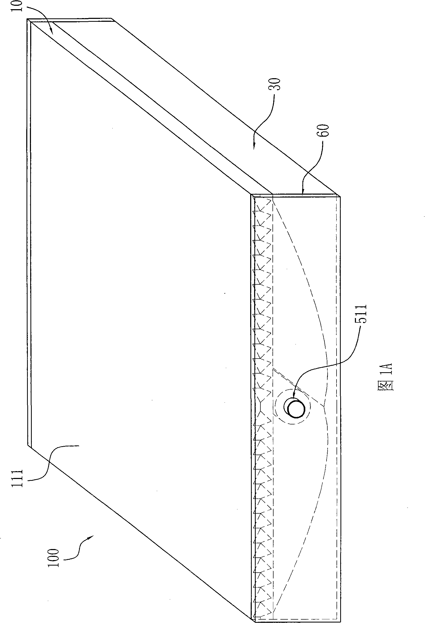
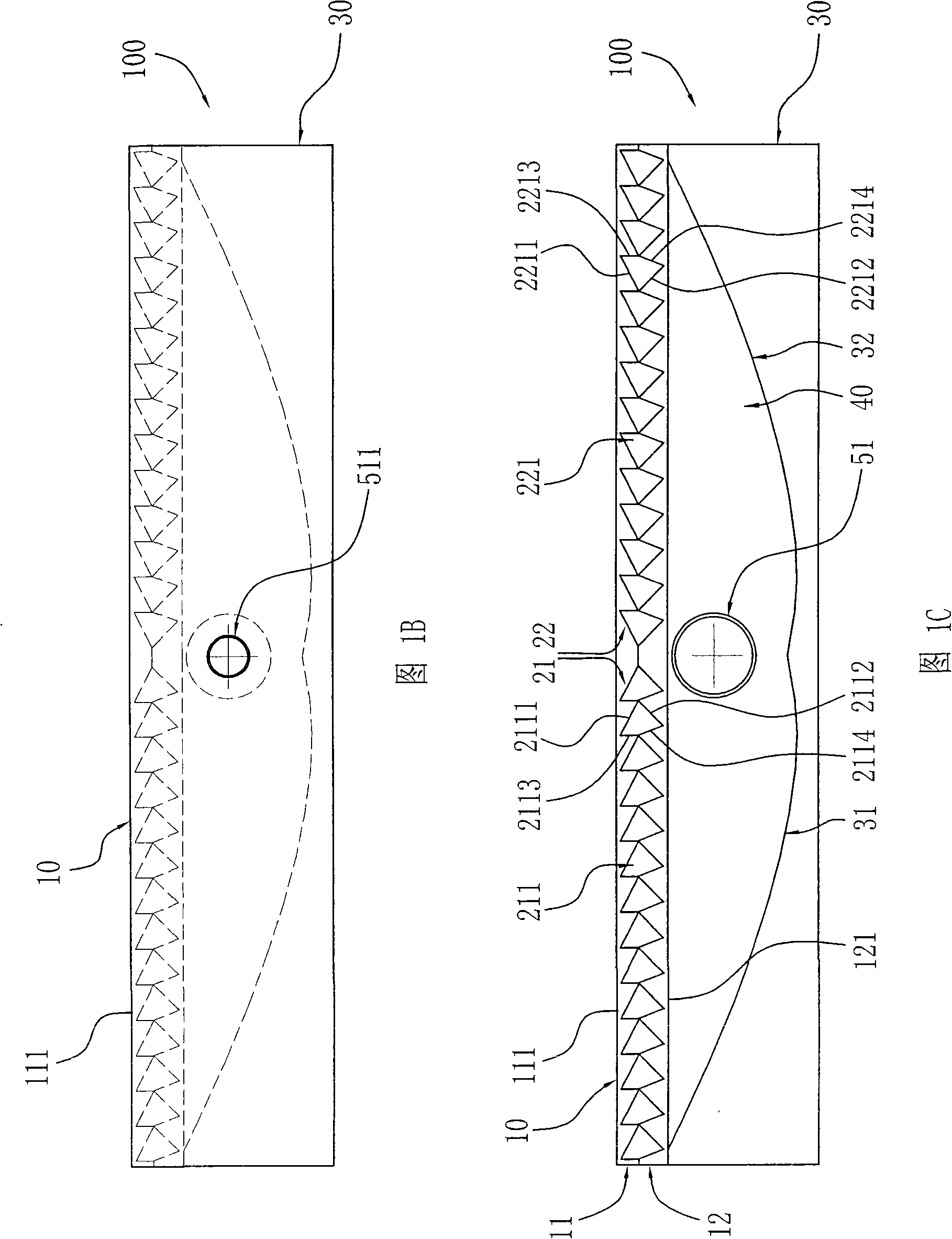
[0037]Referring to Fig. 1A~Fig. 1C, multifunctional light gathering and diffusing plate 100 of the present invention has a bar-shaped plate body 10 that transparent material is made, and it is made of transparent materials such as glass, plexiglass, transparent resin, and its length can be according to determined by actual needs. Specifically, in FIG. 1B and FIG. 1C , the plate-shaped body 10 is joined by an upper plate body 11 and a lower plate body 12 and fixed by bonding or welding. Two sets of left-right symmetrical refraction cavities 21, 22 are arranged in the plate body, and each set of refraction cavities is composed of a plurality of polygonal cavities 211, 221, which are arranged sequentially along the width direction of the plate body, and the multiple refraction cavities of the two groups The polygonal cavities 211, 221 extend from one end to the other along the length direction of the plate-shaped body. The upper plate body 11 and the lower plate body 12 respectiv...

Embodiment 2

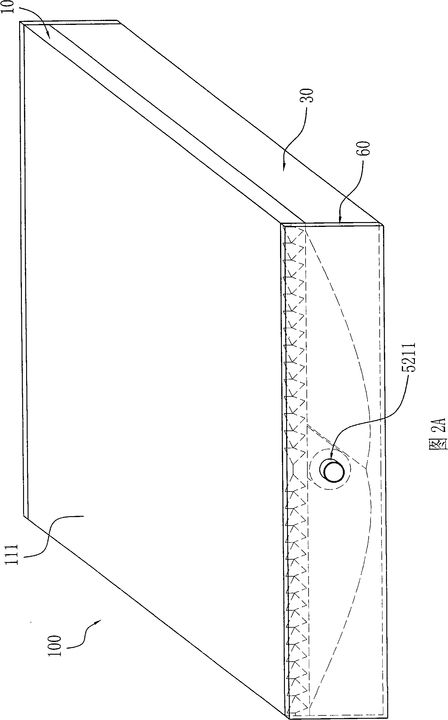
[0042] 2A to 2C, the basic structure is the same as that of Embodiment 1, the difference is that a photoelectric conversion heat collection device 52 is provided on or near the focal line A of the paraboloids 31 and 32 . This photoelectric conversion heat collecting device is made up of heat collecting tube 521 and photovoltaic panel 522, and described photovoltaic panel 522 is obtained by obtaining commercially, and it is closely attached to the outside of heat collecting tube 521, and photovoltaic panel 522 is arranged on the end cover 60 Connected to the output terminals of the solar energy for converting sunlight into electrical energy. The heat collecting tube 521 is made of metal material with high thermal conductivity, and its outer surface is coated with a light-to-heat conversion material with high light absorption. Both ends of the heat collecting tube 521 are provided with conduits 5211 that are sealed and fixed with the end cap 60 and lead out heat. The heat collec...

Embodiment 3

[0044] Referring to Fig. 3A~Fig. 3C, its basic structure is the same as embodiment 1, and difference is, the focal line of described parabola 31,32 or its vicinity is provided with light-emitting device 53, and this light-emitting device is line light source, see as lamp tube Fig. 6, most of the light emitted by the light-emitting device 53 is reflected to the plate body 10 by a parabola, and then the deflection angle becomes the parallel light perpendicular to the plate surface of the plate body and is refracted to the outside; another small part of the light directly passes through the plate body 10 is refracted to the outside at a certain angle, thus forming a plate-shaped parallel light source, which can be used for lighting, background light source, etc., and its light is relatively uniform, soft, and high in brightness.


PUM


Abstract

A multifunctional light condensing and scattering plate comprises a strip body which is made from transparent material and can extend freely and two symmetry refractive cavity groups in the strip body, wherein each refractive cavity group is composed of a plurality of polygon cavities arranged in turn along width, a plurality of polygon cavities of the two refractive cavity groups are extended from one end to another end of the strip plate along length, the lower part of the strip body is provided with a substrate, the upper surface of the substrate are two paraboloids whose focal lines are symmetry, the two paraboloids are light reflection surfaces and form a cavity with the lower surface of the strip body, the focal line A of the paraboloid is on the symmetry plane of the two paraboloids in the cavity, the focal line is provided with a collector tube, a photoelectric conversion collection device or a lighting device. Two ends of the multifunctional light condensing and scattering plate are provided with end covers. The invention combines the functions of solar power generation and heat collection, can densely collect light, attain high photoelectric and photothermal conversion efficiency, low cost, simple installment, maintenance and application and has the ability for generating a collimated light source.

Description

【Technical field】 [0001] The invention relates to the field of optical technology, in particular to a multifunctional light-diverging plate that produces parallel deflection of light and focuses with confocal double parabola reflection. 【Background technique】 [0002] As everyone knows, solar energy is inexhaustible, but people have not yet been able to use it on a large scale. With the reduction of fossil energy such as coal, oil, and natural gas and the continuous rise in price, it has become more and more important for humans to directly obtain energy from solar energy. At present, various solar energy utilization devices have been used, such as photoelectric conversion and photothermal conversion devices. Ordinary light-to-heat conversion equipment is typically equipped with a heat collector tube coated with light absorption and converted into heat energy in multiple glass tubes. The disadvantages are obvious. Because the light energy density per unit area illuminated o...

Claims


Application Information

Patent Timeline
Patent Type & Authority Applications(China)
IPC IPC(8): G02B27/09G02B1/10H02N6/00F24J2/12F24S23/71H02S40/22
CPCY02E10/42Y02E10/40Y02E10/50
Inventor 肖立峰
Owner 肖立峰
Why Eureka
Try Eureka