Air conditioner control system and method

A technology of a control system and a control method, which is applied to air-conditioning systems, heating and ventilation control systems, and control inputs involving air characteristics, etc. Increased energy consumption, simplified steps, and improved operational efficiency

Inactive Publication Date: 2009-01-28
YAMATAKE HONEYWELL CO LTD
View PDF2 Cites 14 Cited by
  • Summary
  • Abstract
  • Description
  • Claims
  • Application Information

AI Technical Summary

Problems solved by technology

[0014] If, as mentioned above, the cold and hot water flowing through the hot and cold water coil exceeds the maximum design flow rate, the delivery power of the pump will increase, resulting in an increase in energy consumption
In addition, for cold and hot water coils, when their design heating (cooling) capacity is exceeded, the exchangeable heat is roughly constant, so, inversely proportional to the flow rate, the heat and cold at the inlet and outlet of the air conditioner The temperature difference of the water is reduced, resulting in low efficiency of the heat source machine and increased energy consumption of the heat source machine
[0015] Originally, in order to achieve the maximum design flow rate when the valve opening of each pipeline system is the largest, manual valves should be used to adjust, but because it takes a lot of man-hours, it will not be done.
[0016] In addition, for systems with large flow requirements, although the opening of the valve can also be used as an indicator for determining water supply control, or the weight of water supply control can be reduced, but this will increase the time and steps of on-site operations
[0017] In addition, in the air-conditioning control systems disclosed in Patent Document 1 and Patent Document 2, even if the cold and hot water flowing through the hot and cold water coil does not exceed the maximum design flow rate, it is impossible to ensure the flow of cold and hot water at the inlet and outlet of the air conditioner. The design temperature is different, so there is a problem of increased energy consumption of the air conditioning control system
As mentioned above, when the design temperature difference cannot be ensured, the efficiency of the heat source machine is low, and the energy consumption of the heat source machine increases
Since the flow of hot and cold water is too large relative to the load of the air conditioner, even if there is no flow of cold and hot water exceeding the maximum design flow, the design temperature difference cannot be ensured

Method used


Image

  • Air conditioner control system and method
  • Air conditioner control system and method
  • Air conditioner control system and method

Examples


no. 1 Embodiment approach

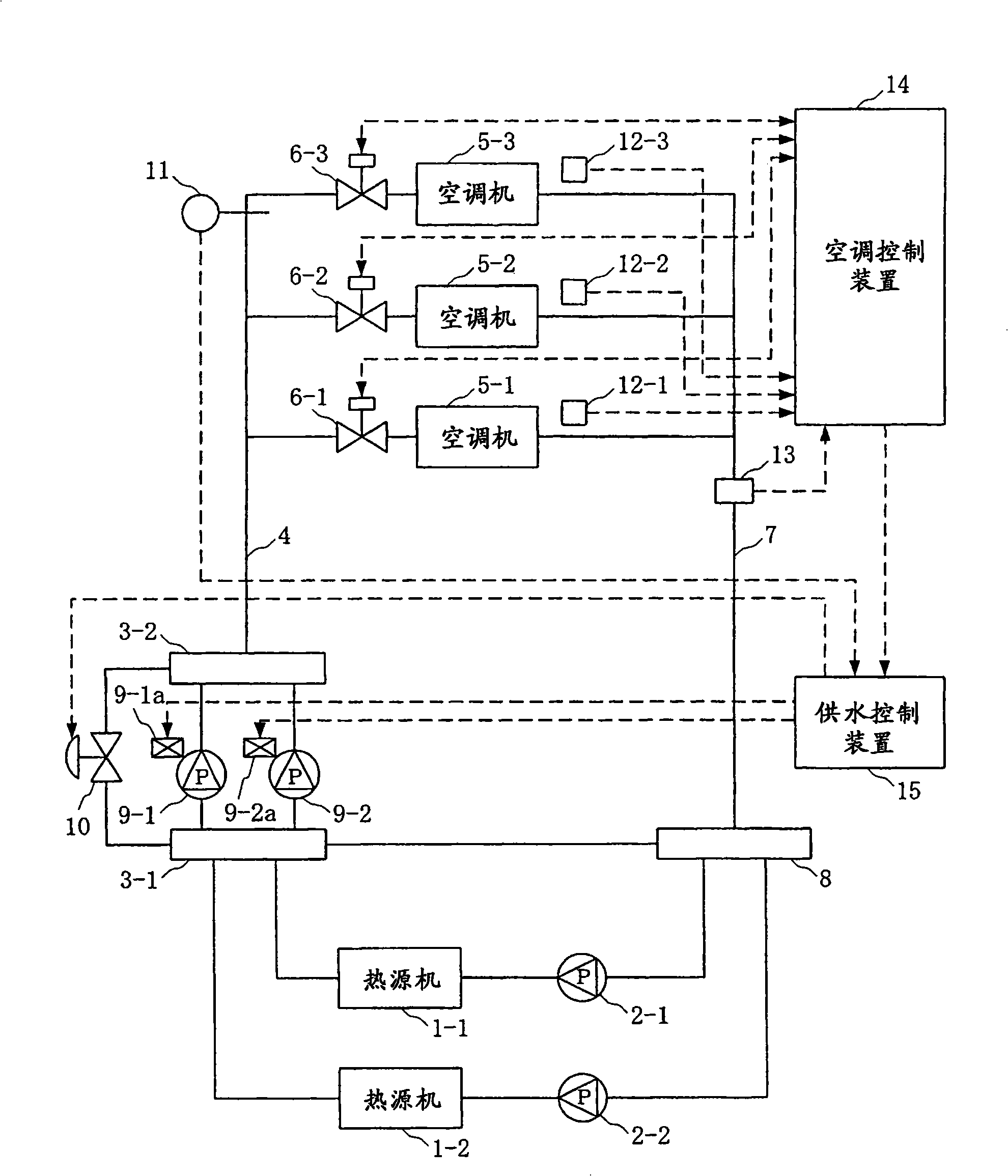
[0038] Hereinafter, embodiments of the present invention will be described with reference to the drawings. figure 1 It is a block diagram showing the structure of the air-conditioning control system of 1st Embodiment in this invention.

[0039] figure 1 The air conditioning control system in the air conditioner includes: heat pumps, refrigerators, boilers, hot and cold water generators that produce hot and cold water (types) of heat source machines 1-1, 1-2; primary pumps 2-1, 2-2, It serves as the auxiliary machine of the heat source machine 1-1, 1-2; multiple water supply headers 3-1, 3-2, which mix the water from multiple heat source machines 1-1, 1-2; the water supply pipeline 4. Air conditioners 5-1~5-3; valves 6-1~6-3, which control the flow of hot and cold water supplied to the air conditioners 5-1~5-3; return water pipe 7; return water header 8. It returns the cold and hot water sent through the return pipe 7 after heat exchange in the air conditioners 5-1 to 5-3 (wi...


PUM


Abstract

The invention provides an air-conditioning control system for inhibiting energy consumption increment, which comprises pumps (9-1, 9-2) conveying cold water and hot water, air conditioners (5-1 to 5-3) receiving the supplied cold water and hot water, valves (6-1 to 6-3) controlling the flow of the cold water and hot water, a flow measuring mechanism arranged inside the valves (6-1 to 6-3), an air-conditioning control device (14) controlling the opening of the valves according to the partial difference of the air supply temperature sent from the air conditioners (5-1 to 5-3) and a set temperature and limiting the opening of the valves when the flow passing through the valves is over the maximum set flow to cause the flow passing through the valves to be maintained below the maximum set flow, and a control device (15) controlling water supply pressure according to the control state of the air conditioners (5-1 to 5-3) determined by the opening of the valves and the flow passing through the valves.

Description

technical field [0001] The invention relates to an air conditioner control system and an air conditioner control method for controlling the flow of cold and hot water flowing into an air conditioner by adjusting the opening degree of a valve. Background technique [0002] In the prior art, for an air-conditioning control system using hot and cold water as a heating medium, a control system for controlling the water supply pressure of the heating medium has been proposed (for example, refer to Patent Document 1 and Patent Document 2). [0003] figure 1 is a block diagram showing the structure of the air-conditioning control system according to the first embodiment of the present invention, and since the overall structure of the air-conditioning control system in the prior art is also the same, it is represented by figure 1 A conventional air-conditioning control system will be described. [0004] The hot and cold water (incoming water) that is pressure-fed by the primary pu...

Claims


Application Information

Patent Timeline
Patent Type & Authority Applications(China)
IPC IPC(8): F24F11/00
CPCF25D17/02F24F11/46F24F11/70F24F11/89F24F2110/10F24F1/00077
Inventor 佐藤庆大
Owner YAMATAKE HONEYWELL CO LTD
Why Eureka
Try Eureka