Overflow-preventing energy-saving pot

An energy-saving pot and anti-overflow technology, applied in the direction of anti-overflow, etc., can solve the problems of poor environmental performance, waste of time, and single function, and achieve the effects of good heat preservation performance, fast heat absorption, and fast heating

Inactive Publication Date: 2009-02-04
洪文明
View PDF0 Cites 12 Cited by
  • Summary
  • Abstract
  • Description
  • Claims
  • Application Information

AI Technical Summary

Problems solved by technology

The traditional microcomputer electric rice cooker manufactured according to the anti-overflow principle of lowering the temperature always controls the temperature of the liquid food in the pot below the boiling point temperature of 100°C when cooking liquid food, so that there will be no overflow phenomenon at all. overflow function? Facts have shown that the anti-overflow principle of traditional microcomputer rice cookers is wrong - this is a congenital defect, so it is impossible to have anti-overflow function
[0007] 2. Waste time
Cooking porridge and soup in such a marathon style seems a bit out of harmony with the fast-paced pace of contemporary life
[0010] 3. Waste of energy
[0011] Traditional microcomputer rice cookers take too long to boil liquid food, waste energy, and have poor environmental performance
[0012] 4. Few varieties, single function, only suitable for cooking
[0014] 5. The amount of boiled liquid food is limited by the scale
[0015] Traditional microcomputer electric rice cookers do not have an anti-spill function. When boiling liquid food, half of the pot space must be reserved to prevent the liquid food in the pot from spilling out of the pot when the temperature ris

Method used


Image

  • Overflow-preventing energy-saving pot
  • Overflow-preventing energy-saving pot
  • Overflow-preventing energy-saving pot

Examples


Embodiment 1

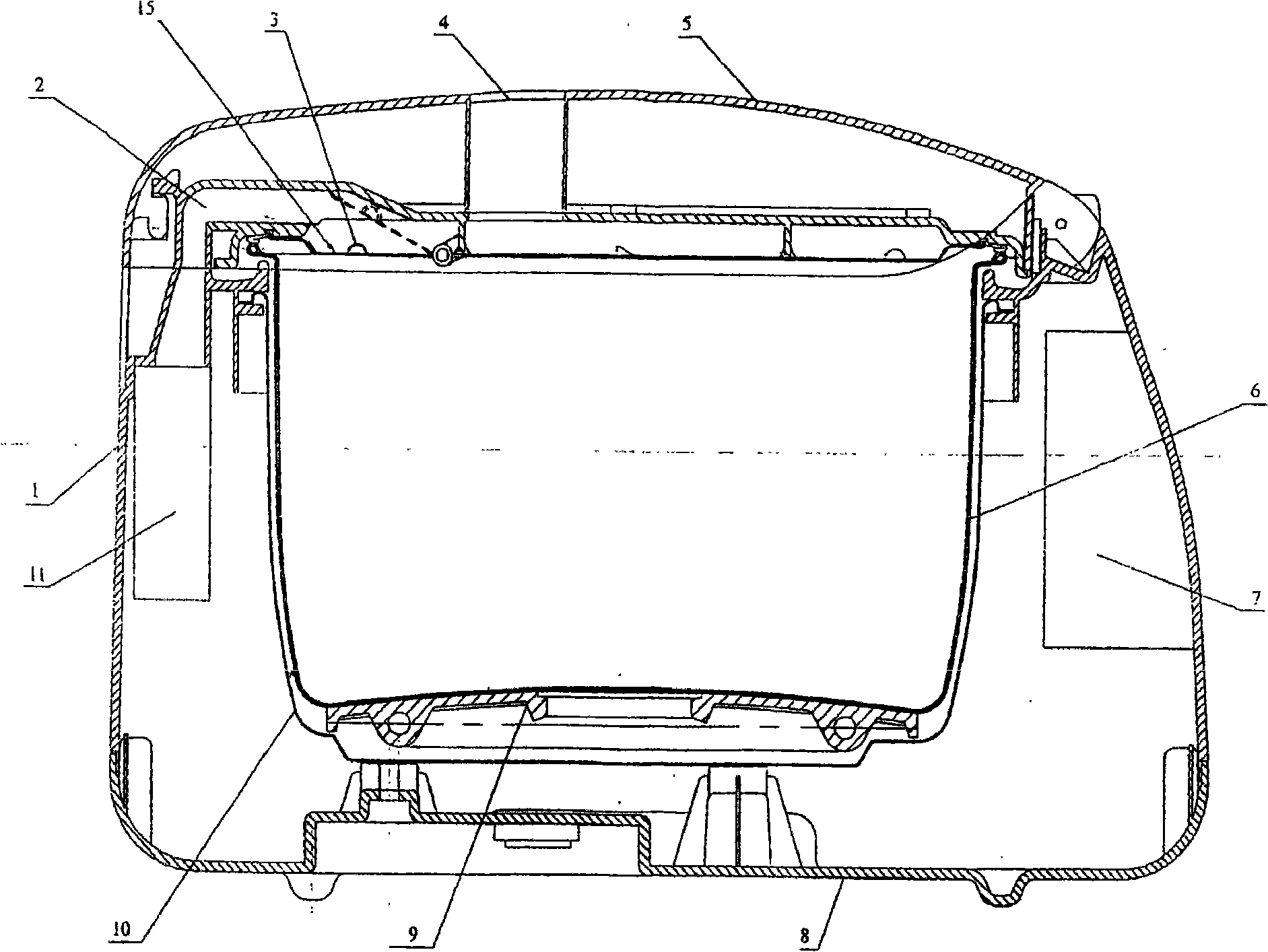
[0089] Embodiment 1: as figure 1 shown. The anti-overflow pot is composed of a pot body 1, an outer pot 10, an inner pot 6, a pot cover 5, an exhaust port 4, a heating element 9, a wire control board 7, a fan 11, an air duct 2, an air spray hole 3, a base 8, Movable wind cover 15 forms. Heating body 9 is equipped with at the bottom of outer pot 10, and wire control board 7 is equipped with at the front portion of pot body 1, and fan 11 is equipped with at the rear portion. When in use, a new generation of computer chips command several thermistors to collect temperature data of the heating element and the inside of the pot respectively, so as to realize the control of the temperature rise and fall of the heating element and the start and stop of the fan; the wind generated by the fan 11 passes through the The air duct 2 sprays into the pot from the blowing hole 3, and blows away the air bubbles generated when the liquid food is boiled, so that the boiled liquid food will not...

Embodiment 2

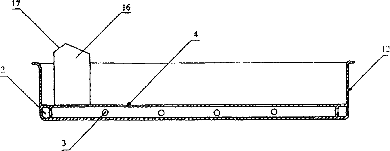
[0090] Embodiment 2: as figure 2 shown. The anti-overflow steamer is composed of a steamer 12, an air duct 16, an air inlet 17, an air duct 2, a blast hole 3, and an air outlet 4. Put the steamer 12 into the inner pot 6, the edge of the air inlet 17 can lift the movable air cover 15, so that the wind generated by the fan 11 is blown into the air inlet 17 and blows into the air duct 2 through the air pipe 16, and finally blows the air from the blowing air. The hole 3 is sprayed into the pot to blow out the bubbles generated when the liquid food is boiled, so that the boiling liquid food will not touch the bottom of the steamer. Therefore, the anti-overflow steamer can also be used to steam food while cooking liquid food, and the color, aroma, taste and shape are all good, the operation is simple, time-saving, energy-saving and hygienic.

Embodiment 3

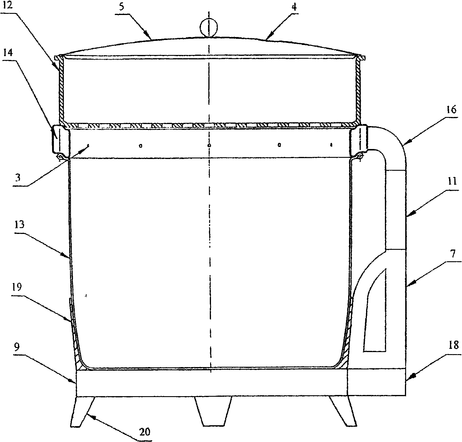
[0091] Embodiment 3: as image 3 shown. The simple anti-overflow pot is composed of a pot body 13, a pot base 19, a heating element 9, a tripod 20, a pot cover 5, an exhaust port 4, a support plate 18, a wire control board 7, a fan 11, an air duct 16, a movable Air duct 14, blast hole 3, steamer 12 are formed. An active air duct 14 is installed on the edge of the upper mouth of the pot body 13, and a support plate 18 is installed on the outside of the heating element 9. On the support plate 18, a wire control board 7 and a blower fan 11 are installed successively, and are welded on the active air duct. The lower end of the air duct 16 on the outside of 14 is connected to the air outlet of the blower fan 11 . Steamer 12 is placed on movable air channel 14. A new generation of computer chips command several thermistors to collect the temperature data of the heating element (chassis) and the pot respectively, so as to realize the control of the temperature rise and fall of the...


PUM


Abstract

The invention belongs to a kitchen cooker pan, and more particularly relates to an overflow-proof method, a manufacture method of an overflow-proof energy-saving pan, a fan, a flue and a wind injection hole, a manufacture method of an overflow-proof steam cooker, a design proposal and a manufacture method used for an insulated energy-saving heating body, three energy-saving methods, a manufacture method used for a conjoined pan, a manufacture method used for the inter boiler of an electric cooker which uses no TFLON coating and has no phenomenon of pan bonding, oil spattering and smoke, and a design method used for a new-generation computer chip. The methods are characterized in that the edge of the pan is provided with the flue; the wind inlet and the wind outlet of the flue are communicated with each other; the flue is provided with a wind injection hole. When in use, the kitchen cooker pan leads the wind generated by the fan to be injected into the pan from the wind injection hole and break the air bubbles generated when the wind flows through the flowing food. According to the experience, no mater what flowing food is cooked, the flowing food is not overflowed out of the pan.

Description

a technical field [0001] The invention belongs to kitchen cooking utensils—pans, and in particular relates to an anti-overflow method, an anti-overflow energy-saving pot, a fan, an air duct, a method for manufacturing an air spray hole, and an anti-overflow steamer Method, a design scheme and manufacturing method of an insulating and energy-saving heating body (chassis, the same below), three energy-saving methods, a manufacturing method of a conjoined pan, a non-stick pan without "Teflon" coating A method for manufacturing an inner pot of an electric rice cooker with oil splashing and no oil fumes, and a method for designing a new generation of computer chips. [0002] Its core components include: pot body (outer shell, the same below), conjoined pot body, pot cover, outer pot, inner pot, fan, air duct, air spray hole, a new generation of computer chips, wire control board, display screen, SCM board, heating element. Two background technology [0003] At present, the most...

Claims


Application Information

Patent Timeline
IPC IPC(8): A47J27/56
Inventor 洪文明
Owner 洪文明
Why Eureka
Try Eureka