
Mixed traction power supply equipment and control method

A traction power supply and control method technology, applied in the direction of output power conversion devices, electrical components, power lines, etc., can solve the problems of large output voltage fluctuations, cost increases, large fluctuations in DC voltage, etc., to achieve the suppression of DC voltage rise, The effect of preventing DC voltage drop, reducing harmonics and reactive power

Inactive Publication Date: 2009-02-11
BEIJING JIAOTONG UNIV +1
View PDF0 Cites 26 Cited by
  • Summary
  • Abstract
  • Description
  • Claims
  • Application Information

AI Technical Summary

Problems solved by technology

[0004] 1. The energy cannot flow in both directions; the energy when the vehicle brakes cannot be fed back to the grid, resulting in a great waste of energy;
[0005] 2. There is no output voltage adjustment function, and the output voltage fluctuates greatly; the fluctuation of AC input voltage and the switching between different operating conditions of the vehicle will cause large fluctuations in DC voltage (500-900V), which is not conducive to the reliable operation of the vehicle at full power ;
[0006] 3. It is necessary to add a bulky brake resistor device, which is not conducive to the light weight of the vehicle
[0007] 4. Larger harmonic pollution to the AC power grid
Therefore, some people propose to simply replace the diode rectifier in the existing traction power supply system with the PWM rectifier, but the PWM rectifier is very complicated in circuit structure and control algorithm compared with the diode rectifier, the cost is greatly increased, and the reliability is reduced
In addition, in order to reduce AC harmonics, power devices are in frequent switching states. If the PWM rectifier works in a high-power state for a long time, the energy loss will be serious.

Method used


Image

  • Mixed traction power supply equipment and control method
  • Mixed traction power supply equipment and control method
  • Mixed traction power supply equipment and control method

Examples


Embodiment Construction

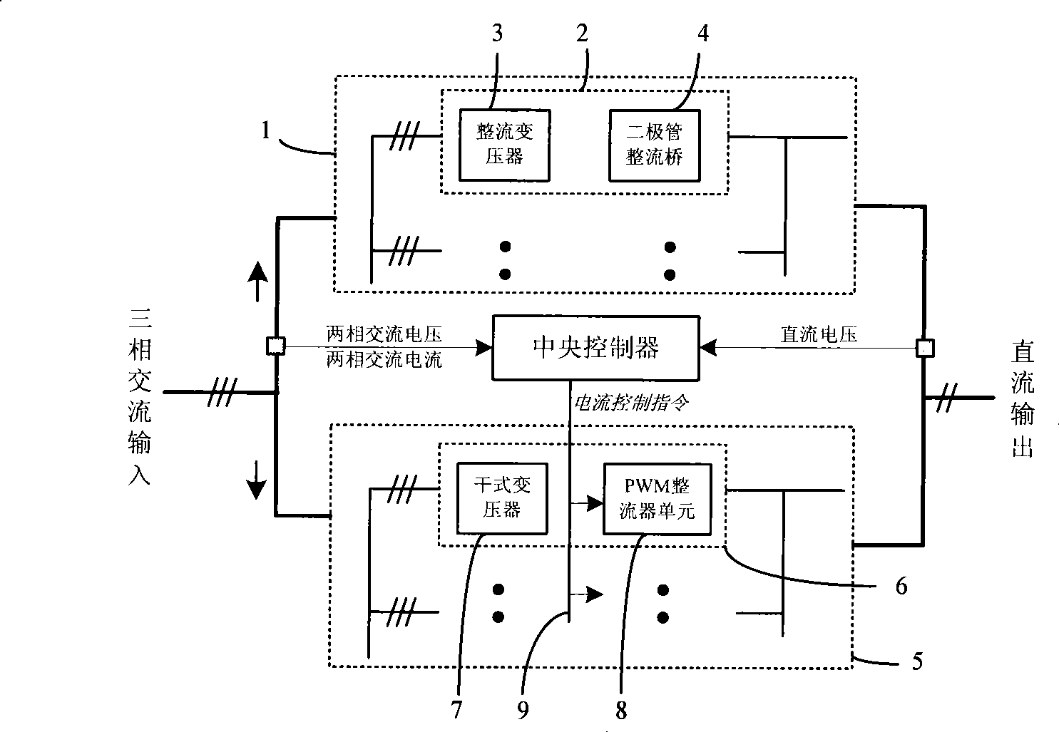
[0028] figure 1 In this embodiment, the rated DC output voltage is 750V, and the entire power supply device is composed of a 24-pulse diode rectifier unit, a PWM rectifier unit and a central controller.

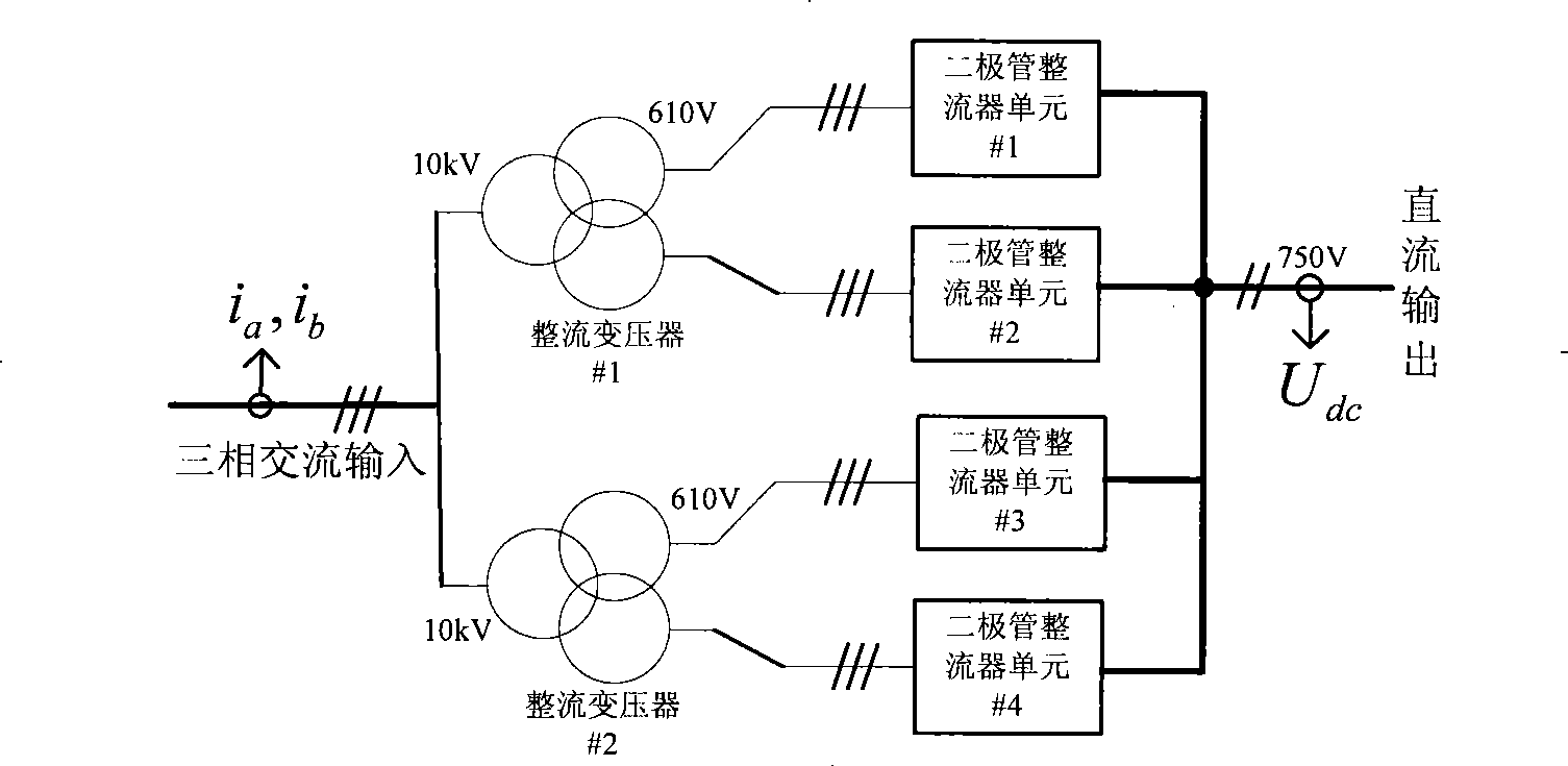
[0029] figure 2 It is a circuit diagram of a 24-pulse diode rectifier unit in this embodiment, which includes 2 phase-shifting rectifier transformers with three windings and 4 diode rectifier bridges. The rectifier transformer adopts epoxy resin casting dry-type transformer, the input voltage of the primary side of the transformer is 10kV, and the output voltage of the secondary side is 610V. The transformer connection mode adopts Dy11d0. In order to realize the 24-pulse rectification output, the primary sides of the two transformers need to adopt the extension triangle connection method.

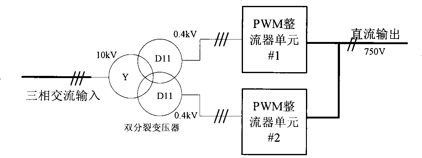
[0030] image 3 is the circuit diagram of the PWM rectifier unit in this embodiment. The PWM rectifier unit only includes a three-winding dry-type transformer and two PWM rectifier un...


PUM


Abstract

The invention relates to a composite type traction power supply device which can enhance the performance of the entire power supply device and reduce the cost. The traction power supply device adopts the technical proposal that the traction power supply device comprises a diode rectification set (1), and is characterized in that a PWM rectification set (5) and a central control unit are also arranged, wherein, the diode rectification set and the PWM rectification set are respectively connected at the alternating current side and the direct current side, so as to form parallel relationship; the central control unit calculates the given values of a d shaft current and a q shaft current of each PWM rectifier unit in the PWM rectification set by detecting the two-phase alternating-current voltage, the two-phase alternating-current and the direct-current output voltage of the diode rectification set, transmits the given values to each PWM rectifier unit in the PWM rectification set through a CAN network and realizes coordination control for the diode rectification set and the PWM rectification set. The invention also discloses a control method of the device.

Description

technical field [0001] The invention relates to a power supply conversion device and a control method, in particular to a hybrid traction power supply device and a control method for traction power supply of rail transit vehicles. Background technique [0002] The development of urban rail transit is not only an effective measure to alleviate urban traffic congestion, but also an inevitable requirement for improving the urban living environment and promoting sustainable urban development. [0003] At present, my country's urban rail transit power supply devices use diode rectifiers, and the power supply voltage is 750V or 1500V. This kind of diode rectifier has been used for decades. Its biggest advantage is its simple structure and reliable performance. Some shortcomings are also becoming more and more prominent: [0004] 1. The energy cannot flow in both directions; the energy when the vehicle brakes cannot be fed back to the grid, resulting in a great waste of energy; ...

Claims


Application Information

Patent Timeline
IPC IPC(8): B60M3/00B60M3/06H02M7/04H02M7/06H02M5/10H02M7/12H02M1/42H02M7/48
Inventor 刘志刚张钢沈茂盛赵明花卢西伟狄威贾利民牟富强王磊刁利军李哲峰林文立梅樱罗荣娅
Owner BEIJING JIAOTONG UNIV
Features
  • Generate Ideas
  • Intellectual Property
  • Life Sciences
  • Materials
  • Tech Scout
  • Unparalleled Data Quality
  • Higher Quality Content
  • 60% Fewer Hallucinations
Learn More