Cable type differential for detection vehicle

A technology for differentials and detection vehicles, applied in differential transmissions, motor vehicles, belts/chains/gears, etc., can solve the problems of small launch payload, occupy storage space, and high processing costs, and increase the launch payload. , Wide range of applications, the effect of reducing processing costs

Inactive Publication Date: 2009-02-11
HARBIN INST OF TECH
View PDF0 Cites 2 Cited by
  • Summary
  • Abstract
  • Description
  • Claims
  • Application Information

AI Technical Summary

Problems solved by technology

[0003] The purpose of the present invention is to solve the problem that the existing gear differential for exploration vehicles adopts bevel gear transmission, which has high processing cost and large mass. The differential housing is installed inside the load platform to occupy the internal storage space of the load platform and launch payload Small problems, and then provide a rope differential for detection vehicles

Method used


Image

  • Cable type differential for detection vehicle
  • Cable type differential for detection vehicle
  • Cable type differential for detection vehicle

Examples


specific Embodiment approach 1

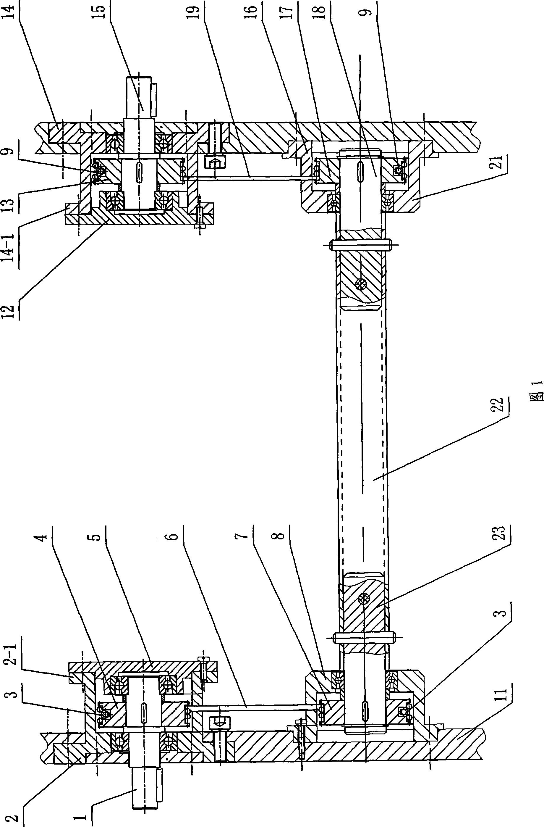
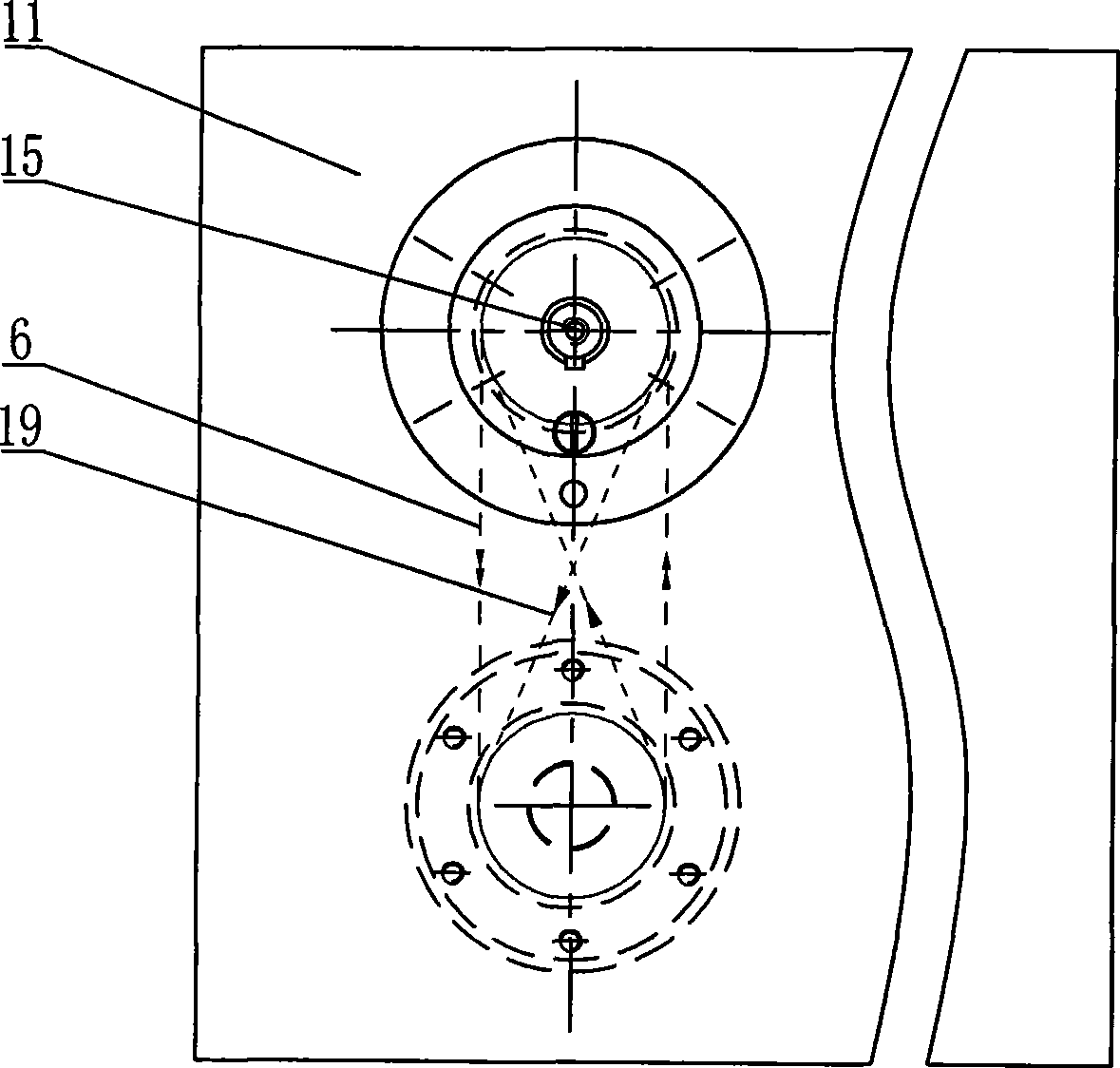
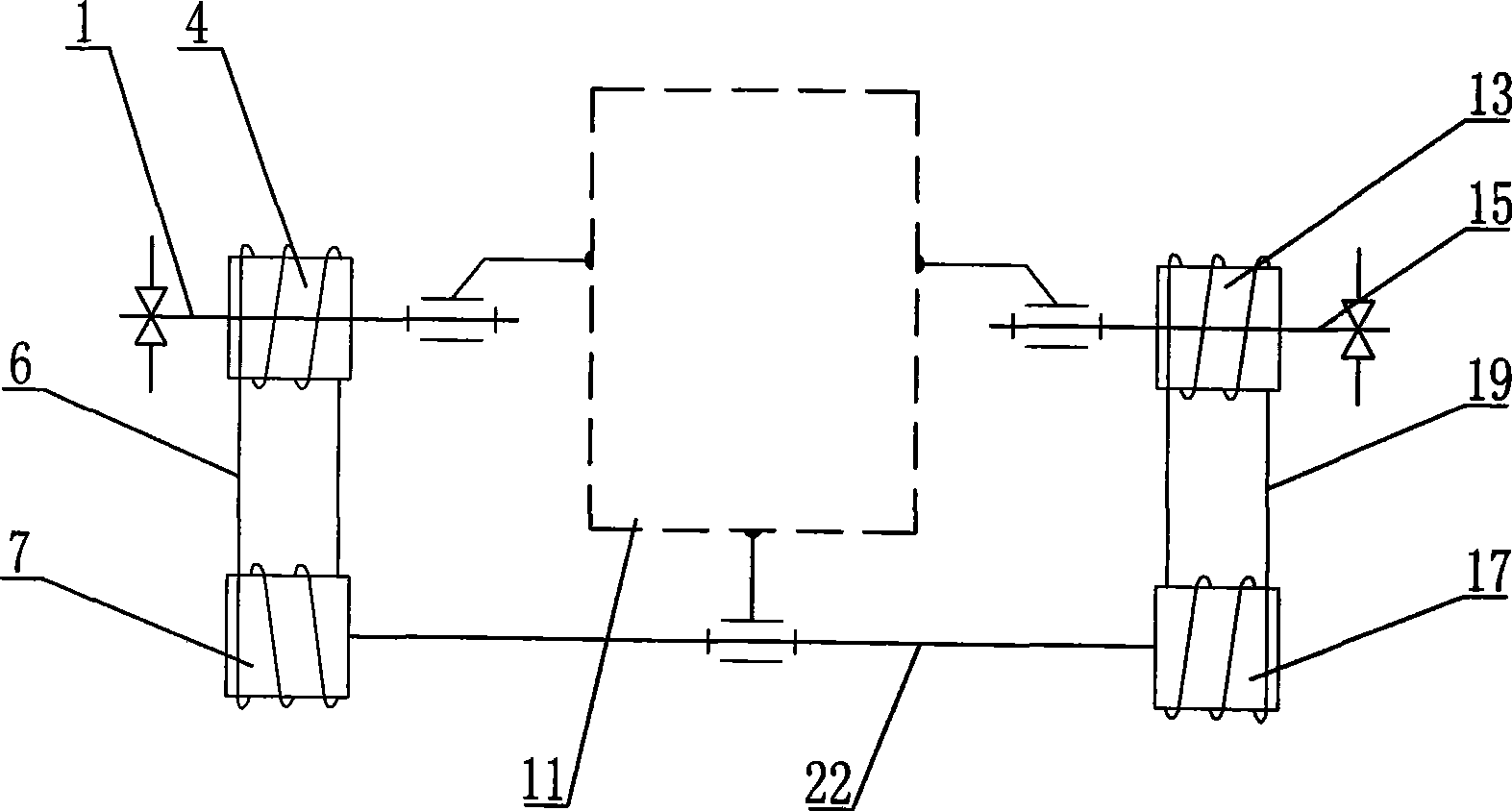
[0007] Specific implementation mode one: in conjunction with Fig. 1~ image 3 This embodiment is described. This embodiment is composed of a co-directional transmission unit, a reverse transmission unit, a hollow shaft 22 and a load platform 11. The co-directional transmission unit and the reverse transmission unit are installed at both ends of the hollow shaft 22 respectively. The same-direction transmission unit includes the same-direction driving wire pulley 4, the same-direction driven wire pulley 7, the first input shaft 1, the same-direction support sleeve 2, the same-direction steel wire rope 6, the same-direction end cover 5, and the same-direction bearing end cover 8 and the same direction connecting short shaft 23; the same direction support sleeve 2 is installed on the first input shaft 1, and the same direction end cover 5 is fixed on the small flange end surface 2-1 of the same direction support sleeve 2, And the first input shaft 1 is rollingly matched with the s...

specific Embodiment approach 2

[0008] Embodiment 2: This embodiment is described with reference to FIG. 1 . The axes of the first input shaft 1 and the second input shaft 15 in this embodiment are on the same straight line. Such setting ensures the symmetrical installation of the suspension on both sides and the better work of the rope differential. Other compositions and connections are the same as in the first embodiment.

specific Embodiment approach 3

[0009] Specific embodiment three: This embodiment is described in conjunction with Fig. 1. The co-directional transmission unit of this embodiment is also added with two co-directional steel wire briquetting blocks 3, and the two co-directional steel wire briquetting blocks 3 are installed on the co-directional driving steel wires respectively. Wheel 4 and the same direction driven wire wheel 7. Such setting is used to fix the wire rope to prevent the wire rope from falling off. Other compositions and connections are the same as in the first embodiment.


PUM


Abstract

A rope differential used for a probe vehicle relates to a differential used for a probe vehicle, and solves the problem that the existing gear differential used for a probe vehicle adopts a bevel wheel for transmission, which has high processing cost and large mass owing, and a differential shell is arranged in a load platform, which occupies the inside storage space of the load platform and emits little effective load. The invention is composed of a co-rotating transmission unit, a reverse transmission unit and a hollow shaft (22); the co-rotating transmission unit and the reverse transmission unit are arranged at the two ends of the hollow shaft respectively; a co-rotating driven wire wheel (7) is arranged under a co-rotating driving wire wheel (4) which is connected with the co-rotating driven wire wheel (4) by a co-rotating wire rope (6); a reverse driven wire wheel (17) is arranged under a reverse driving wire wheel (13) which is connected with a reverse driven wire wheel (17) by a reverse wire rope (19). The differential has the advantages of reducing the space occupying of the load platform, being easy to arranged, having little mass and wider application scope.

Description

technical field [0001] The invention relates to a detection vehicle differential. Background technique [0002] The differential is essential for a planetary rovers with a two-point supported load platform, and it is an important part of the locomotion system. The terrain on the surface of the planet is rough and the structure is complex and changeable. The differential can reduce the impact of the suspension swing on both sides on the loading platform, ensure the relative stability of the loading platform during driving, and ensure the normal operation of scientific instruments on the loading platform of the rover. Most of the currently developed exploration vehicles use symmetrical straight-toothed bevel gear differentials, and its structural principle is the same as that of planetary bevel gear differentials commonly used in automobiles, that is, the rotation of the planetary bevel gears around the left and right half shafts reduces the load on both sides of the suspensio...

Claims


Application Information

Patent Timeline
IPC IPC(8): F16H48/00B62D57/024F16H48/12F16H48/38
Inventor 高海波邓宗全张朋张禹陶建国
Owner HARBIN INST OF TECH
Why Eureka
Try Eureka