Chain boiler plant for burning multi-biomass fuels

A biomass fuel and chain boiler technology, applied in the direction of solid fuel combustion, combustion methods, combustion equipment, etc., can solve the problems of chain boiler load instability, boiler load adjustment difficulties, etc., to achieve the effect of easy boiler load and easy adjustment

Inactive Publication Date: 2009-02-11
HARBIN INST OF TECH
View PDF0 Cites 21 Cited by
  • Summary
  • Abstract
  • Description
  • Claims
  • Application Information

AI Technical Summary

Problems solved by technology

[0003] In order to solve the problems of unstable load of the chain boiler and difficult adjustment of boiler load when the existing chain boiler burns biomass, the present invention proposes a chain boiler device for burning multiple biomass fuels

Method used


Image

  • Chain boiler plant for burning multi-biomass fuels
  • Chain boiler plant for burning multi-biomass fuels

Examples


specific Embodiment approach 1

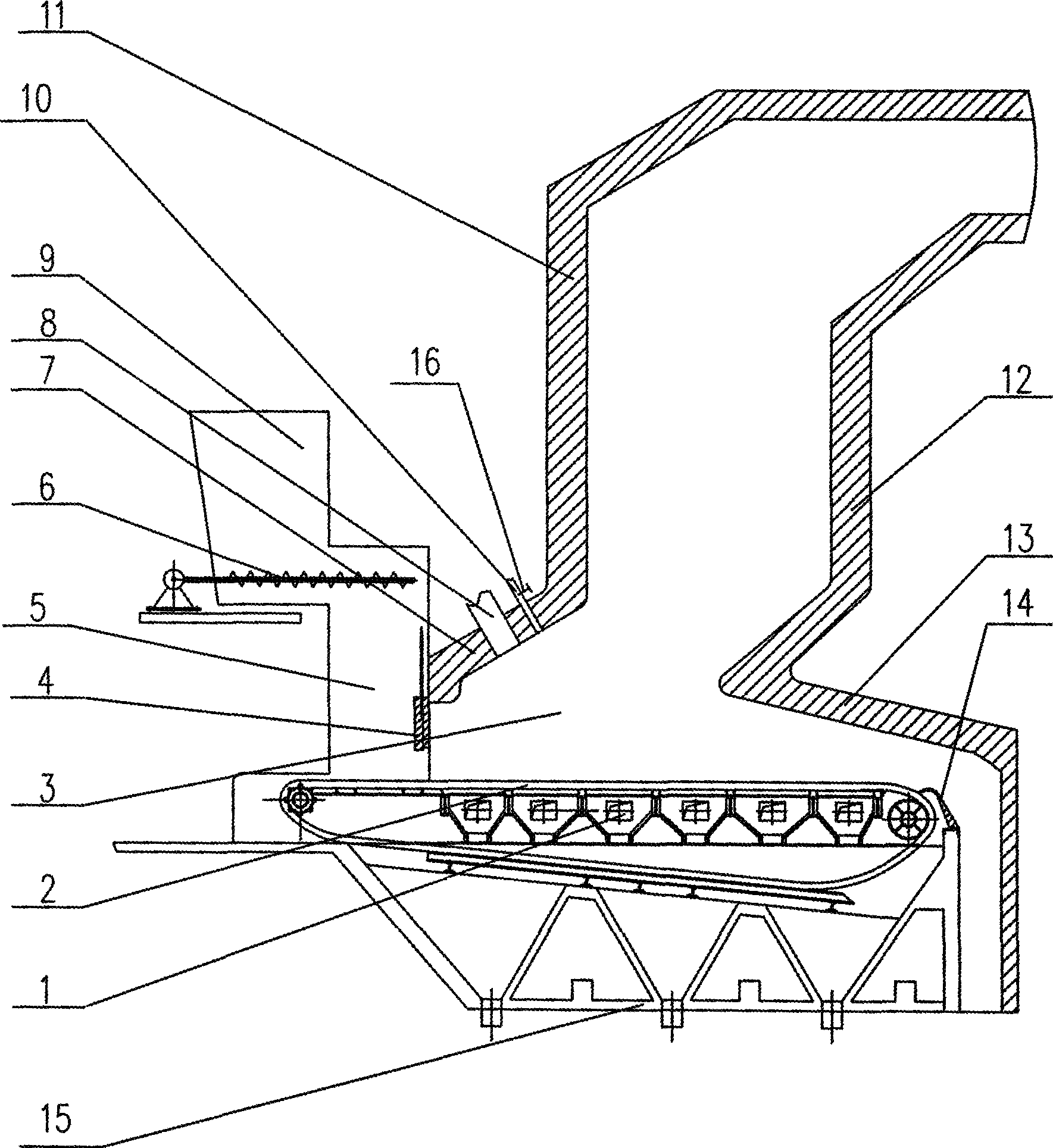
[0007] Specific implementation mode one: as figure 1 As shown, the chain boiler device for burning multiple biomass fuels in this embodiment includes a boiler base 15, a fire grate 2, a front arch 7, a rear arch 13, a front wall 11, a rear wall 12, a biomass baffle 4, Reamer 6, biomass upper hopper 9, biomass lower hopper 5 and air distribution chamber 1, the lower end of the biomass upper hopper 9 communicates with the upper end of the biomass lower hopper 5, and the biomass upper hopper 9 is connected to the biomass The joint of the lower hopper 5 is horizontally equipped with a hinged dragon 6, the air distribution chamber 1 is arranged on the fire grate 2, and the fire grate 2 is arranged on the upper end of the boiler base 15, the front wall 11, the front arch 7, the biomass lower hopper 5, The fire grate 2, the rear arch 13, and the rear wall 12 enclose the furnace 3, and the biomass baffle 4 is located between the front arch 7 and the fire grate 2 and is arranged in the...

specific Embodiment approach 2

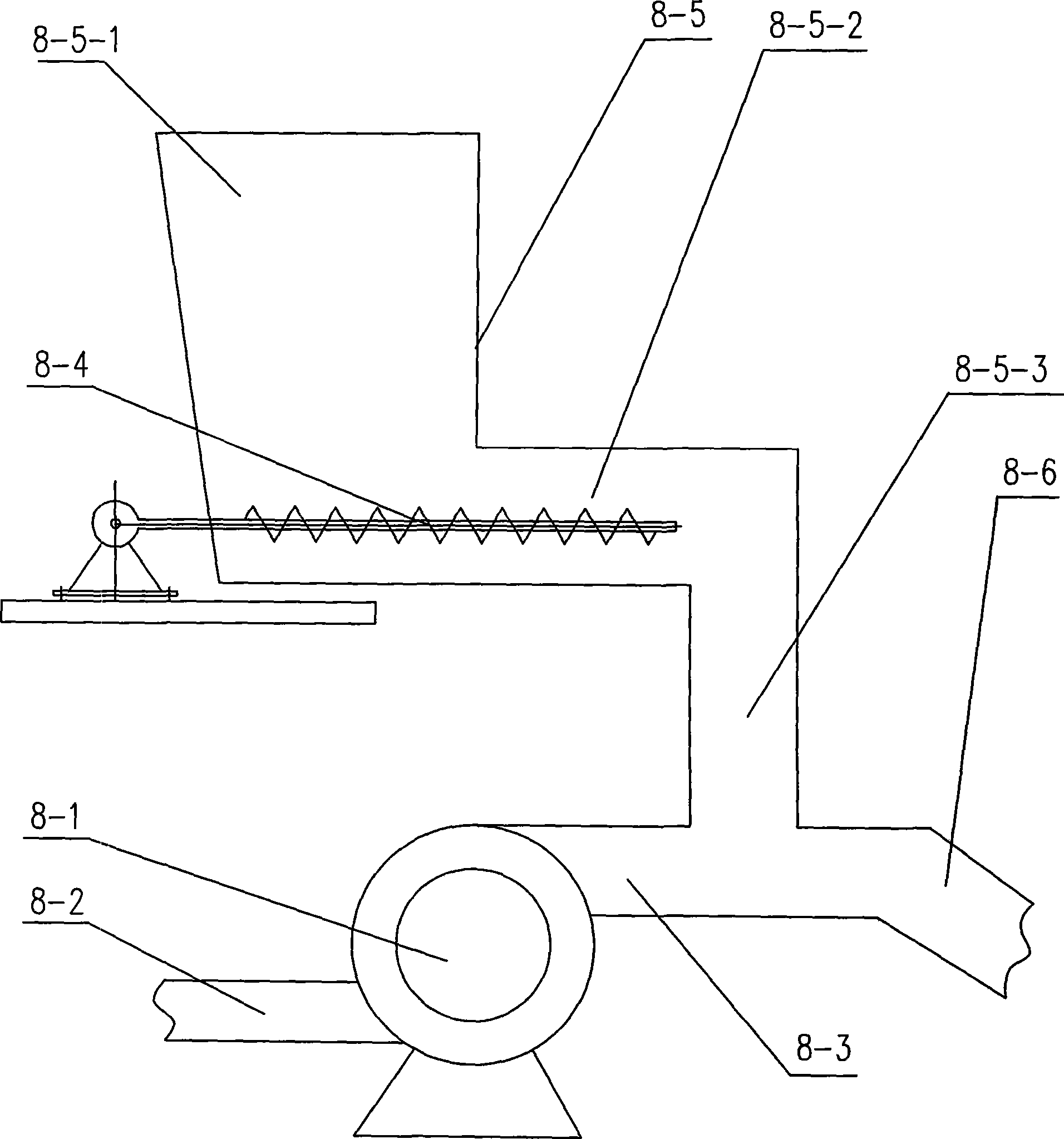
[0009] Specific implementation mode two: as figure 1 and figure 2 As shown, the arched biomass spout device 8 in this embodiment consists of a feeding fan 8-1, a feeding air inlet pipe 8-2, a feeding air outlet pipe 8-3, a feeding hinge 8-4, and a powdery biomass hopper. 8-5 and arched biomass spout 8-6, the powdery biomass hopper 8-5 is composed of upper hopper 8-5-1, horizontal section 8-5-2 and lower hopper 8-5-3, The lower end of the upper hopper 8-5-1 communicates with the upper end of the lower hopper 8-5-3 through the horizontal section 8-5-2, and the feeding hinge 8-4 is horizontally arranged in the horizontal section 8-5-2. The air inlet pipe 8-2 communicates with the feeding fan 8-1, the feeding fan 8-1 communicates with the feeding air outlet pipe 8-3, and the lower end of the lower hopper 8-5-3 and the feeding air outlet pipe 8-3 are all connected with the upper arch. The biomass spout 8-6 communicates, and the biomass spout 8-6 on the arch communicates with the...

specific Embodiment approach 3

[0010] Specific implementation mode three: as figure 1 As shown, the boiler device in this embodiment further includes a slag stopper 14, and the slag stopper 14 is installed between the rear end of the fire grate 2 and the boiler base 15. The slag stopper 14 prevents ash from entering the bottom of the fire grate. Other compositions and connections are the same as those in Embodiment 1 or 2.

[0011] working principle:

[0012] Biomass fuel (such as wood branches, wood blocks, etc.) drops from the silo to the hinge dragon 6 through the biomass upper hopper 9, and two to three hinge dragons are arranged along the width direction of the boiler, and the biomass fuel is pushed to the biomass through its rotation. In the material lower hopper 5, the biomass fuel will fall on the fire grate 2 through the biomass lower hopper 5. Blocked by the biomass baffle plate 4, the rotating fire grate 2 takes away a certain thickness of block biomass fuel. Biomass fuel enters the furnace 3...


PUM


Abstract

A chain-grate boiler device for burning a plurality of biomass fuels relates to a chain-grate boiler device. The chain-grate boiler solves the problems of unstable chain-grate boiler load and being difficult in adjusting the boiler load when the existing chain-grate boilers burn biomass. In the device, a biomass nozzle device (8) on an arch is obliquely arranged on a front arch (7) and is communicated with a hearth (3), a secondary air nozzle (10) on the arch is positioned at the slanting upper part of the biomass nozzle device (8) on the arch, the secondary air nozzle (10) on the arch is arranged on the front arch (7) and is communicated with the hearth (3), and the secondary air nozzle (10) on the arch is provided with an airflow regulating valve (16). The chain-grate boiler device adopts a combined feeding device composed of a biomass blanking hopper, the biomass nozzle device on the arch and the secondary air nozzle on the arch, thus causing the load of the chain-grate boiler for burning the biomass fuels to be stable and being convenient for adjusting the boiler load.

Description

technical field [0001] The invention relates to a chain boiler device, in particular to a chain boiler device for burning various biomass fuels. Background technique [0002] As the price of fossil fuels such as oil and natural gas climbs, renewable energy will gain momentum. According to the research of the International Institute of Applied Systems Analysis, in the middle of the 21st century, renewable energy mainly composed of solar energy and biomass energy will account for more than 30% of the world's energy composition, and it will be the main source of energy after coal slurry, oil and natural gas. alternative energy source. The development of renewable energy has become a hot issue in the world, and it is an inevitable choice for the development of sustainable energy. Compared with fossil energy, biomass energy has great advantages: its CO 2 The net emission is zero, which can effectively alleviate the greenhouse effect. Because of its low sulfur and nitrogen cont...

Claims


Application Information

Patent Timeline
Patent Type & Authority Applications(China)
IPC IPC(8): F23B40/00F23L9/02F23K3/00
Inventor 李争起李瑞扬韩云峰陈智超刘春龙王琳柳建华秦裕琨
Owner HARBIN INST OF TECH
Why Eureka
Try Eureka