Chaos colidar anti-collision system for automobile and method thereof

A chaotic laser and anti-collision system technology, applied in radio wave measurement systems, electromagnetic wave re-radiation, utilization of re-radiation and other directions, can solve the problems of difficulty in broadband chaotic signals, low distance resolution, and high cost of coding equipment, and achieve good self-efficacy. The effect of identifying ability, improving anti-interference ability, and avoiding mutual interference problems

Inactive Publication Date: 2009-02-11
TAIYUAN UNIV OF TECH
View PDF4 Cites 33 Cited by
  • Summary
  • Abstract
  • Description
  • Claims
  • Application Information

AI Technical Summary

Problems solved by technology

Among them, the random code modulation random signal radar system is limited by the random code length and modulation rate and the distance resolution is low; the laser radar system using coding equipment has a ...

Method used


Image

  • Chaos colidar anti-collision system for automobile and method thereof
  • Chaos colidar anti-collision system for automobile and method thereof
  • Chaos colidar anti-collision system for automobile and method thereof

Examples


specific Embodiment approach 1

[0034] Implementation of Chaotic LiDAR Vehicle Collision Avoidance System

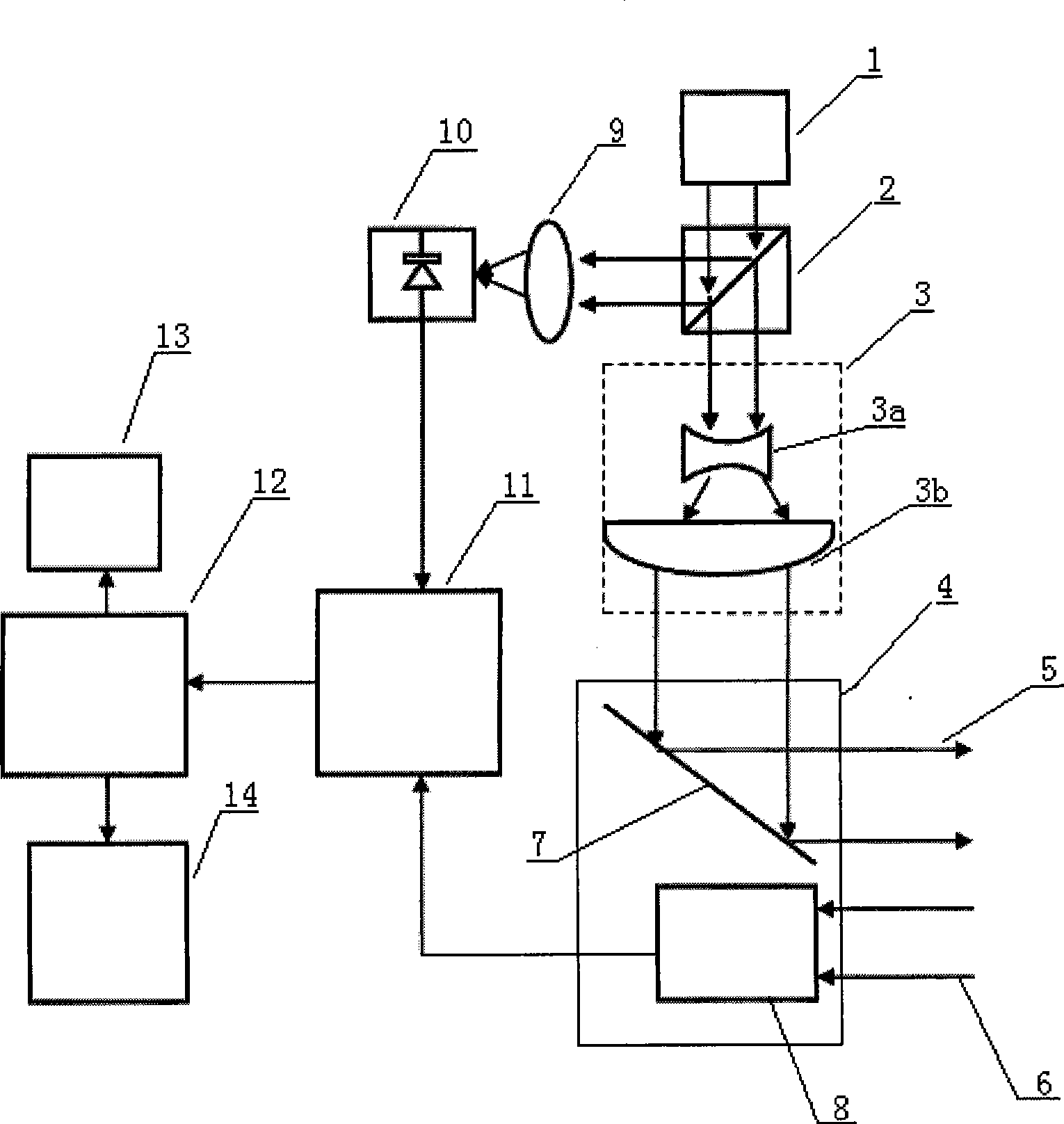
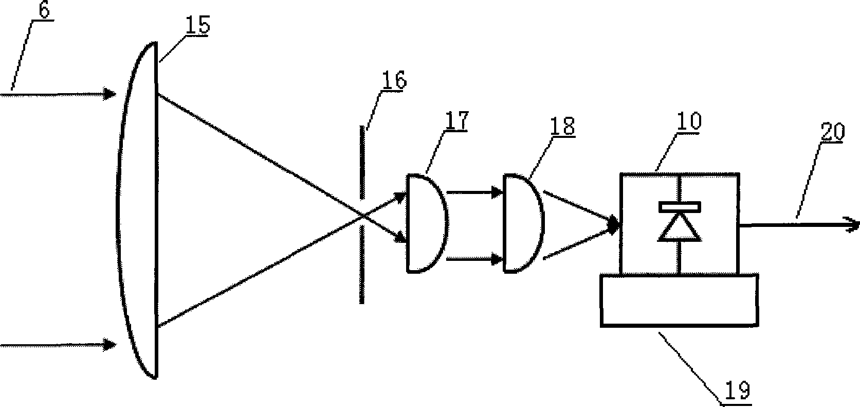
[0035] Such as figure 1 As shown, the chaotic laser generated by the chaotic laser 1 enters the beam splitter 2, and the beam splitter 2 divides the chaotic laser into two beams: transmitted light and reflected light. The optical lens 9 and the photodetector 10, the photodetector 10 converts the reference beam into an electrical signal and inputs it to the digital correlator 11, the transmitted light of the beam splitter 2 is input to the beam expander 3 for beam expansion, and the beam expander 3 The output is input to the scanning mirror 7, and the chaotic laser 5 output by the scanning mirror 7 is used as a detection light signal, and the target obstacle is scanned and detected under the drive of the scanning platform 4, and the detection signal beam is reflected after encountering the target obstacle. The receiver 8 receives the reflected echo signal 6 and converts it into an electrical signal thr...

specific Embodiment approach 2

[0050] A method for implementing a chaotic LiDAR automotive collision avoidance system, see Figure 5 , the implementation method steps are as follows:

[0051] First, system initialization. First, initialize the system, and place the scanning mirror at the initial position, so that the initial angle of the laser scanning is at the 0 degree position of the scanning range.

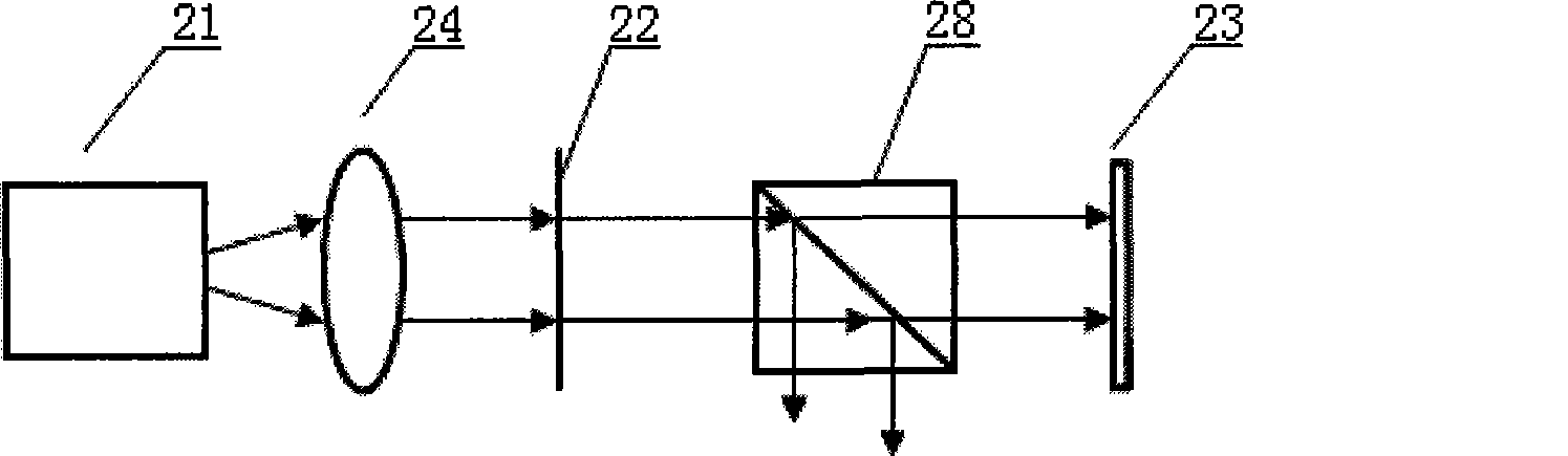
[0052] Second, the detection of target obstacles. Turn on the power of the laser I 21 or the laser II 25, and the chaotic laser 1 generates chaotic laser through optical feedback. After the chaotic laser is input into the beam splitter 2, it is divided into two beams by the beam splitter 2, and the reflected light of the beam splitter 2 is used as a reference signal beam, which is sequentially input to the converging optical lens 9 and the photodetector 10, and the photodetector 10 converts the reference beam Converted into an electrical signal and input to the digital correlator 11, the transmitted ligh...


PUM


Abstract

The invention discloses an automobile chaotic laser radar anti-collision system and the method thereof. The automobile chaotic laser radar anti-collision system is characterized in that the chaotic laser light produced by a chaotic laser is taken as a radar signal, and is divided into two beams by a beam splitter; one beam is taken as a reference signal, and the other beam is taken as an emission signal for scanning detection to an objective obstacle through a scanning device; a receiver is utilized for respectively receiving the reference signal and an echo signal reflected by an object; the delay time of the echo signal is obtained by carrying out the correlation operation to the echo signal and the reference signal, thereby further calculating out and obtaining the distance of the objective obstacle; and at the same time, the relative velocity of an automobile and the objective obstacle is calculated out and obtained according to distance differences of definitive time intervals. The invention uses the chaotic laser light produced by an optical-feedback semiconductor laser as a laser radar signal, has the advantages of high distance accuracy, strong anti-interference capacity, simple structure and the like, and is applicable to various automobiles.

Description

technical field [0001] The invention relates to a radar vehicle anti-collision system and method, in particular to a system and method for realizing vehicle anti-collision by using a chaotic laser radar system. technical background [0002] The laser radar ranging technology in the existing vehicle laser radar system is mainly the pulse laser radar ranging technology and the continuous light modulation ranging technology. [0003] Pulse laser radar ranging technology is to use the range finder to send a laser pulse to the target, the pulse is reflected back to the optical sensor element of the range finder by the detection target, and the round-trip time t of the pulse light is recorded by the timer to obtain the target distance. Such as: Harbin Institute of Technology proposed a one-dimensional scanning laser radar car anti-collision system (CN1847881A) and Tsinghua University proposed a vehicle-mounted scanning laser radar detection system and its method for detecting dan...

Claims


Application Information

Patent Timeline
IPC IPC(8): G01S17/93
Inventor 王云才王安帮龚天安
Owner TAIYUAN UNIV OF TECH
Why Eureka
Try Eureka