
Real-time emulation control method based on triggering-delay

A control method and real-time simulation technology, applied in general control systems, control/regulation systems, instruments, etc., can solve the problems that cannot be used to verify the performance of the control development board, the storage space control development board is uneconomical, and the control performance of the closed-loop system can be changed. problems, to achieve the effect of saving experimental costs, improving development efficiency, and verifying reliability

Inactive Publication Date: 2009-02-11
SHANGHAI JIAO TONG UNIV
View PDF0 Cites 11 Cited by
  • Summary
  • Abstract
  • Description
  • Claims
  • Application Information

AI Technical Summary

Problems solved by technology

However, this kind of real-time system lacks compatibility in hardware and cannot be used on many control development boards (especially those designed by developers), so it cannot be used to verify the performance of such control development boards (such as main frequency, The relationship between the D / A conversion rate and the sampling period); in addition, the control executable program generated by the real-time code generation tool is not a streamlined code, which is uneconomical for the control development board with limited storage space
More importantly, because the real-time simulation process mentioned in the article requires five interface circuits to connect the PC and the industrial computer, the cost of the experiment increases, and because the analog input and output circuits have conversion delays and errors, they will be in the closed-loop control loop. Introducing additional errors in the control performance of the closed-loop system

Method used


Image

  • Real-time emulation control method based on triggering-delay
  • Real-time emulation control method based on triggering-delay
  • Real-time emulation control method based on triggering-delay

Examples


Embodiment

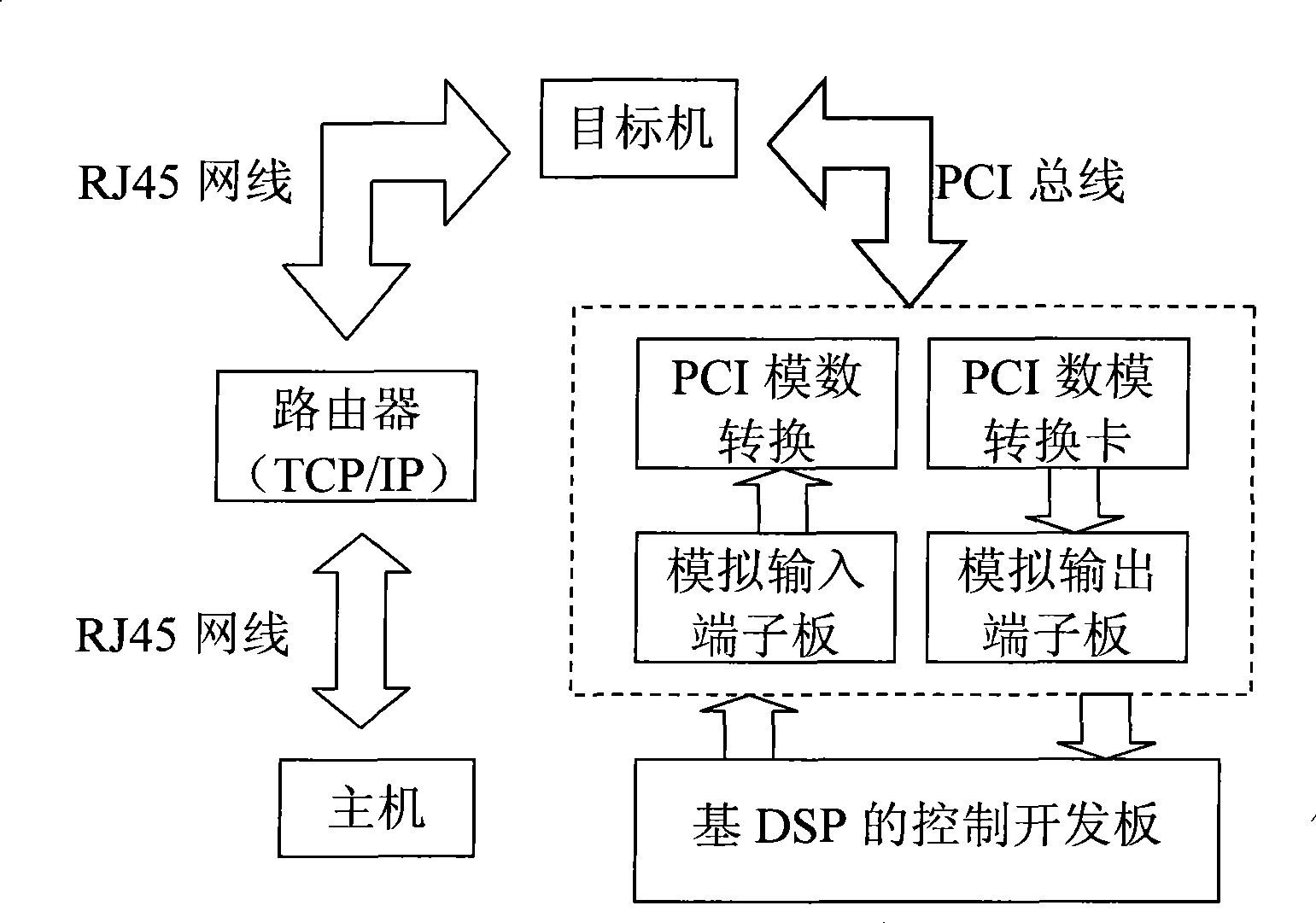
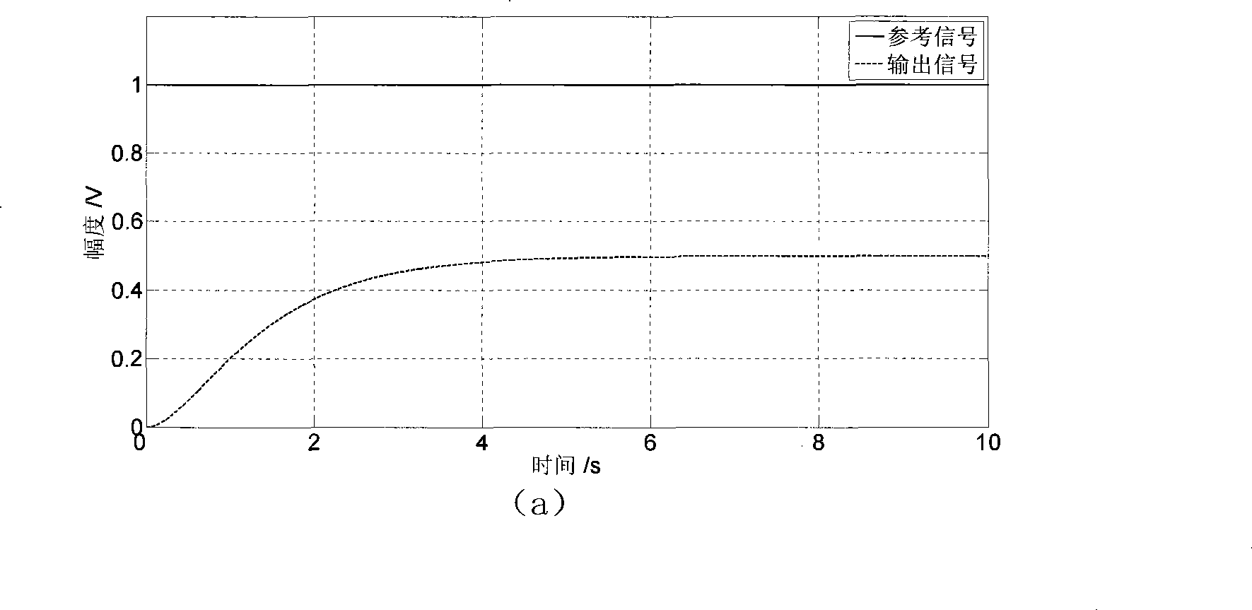
[0041] Embodiment: for the control development board TMS320LF2407 of the TI (Texas Instruments) company that often adopts in a real-time simulation control system, the digital-to-analog conversion card PCI1720U and the analog-to-digital conversion card PCI1710HG of two common PCs and Advantech (researching Chinese company), adopt The real-time simulation control method based on trigger-delay is introduced, and the specific implementation steps are introduced.

[0042] ①. Establish a hardware development platform

[0043] Connect the host machine and the target machine: Configure two ordinary PCs equipped with floppy disk drives. One is the host machine and the other is the target machine. Based on the TCP / IP protocol, the target machine and the host machine are connected to the router through the RJ45 network cable in the local area network to realize the communication between the two.

[0044] Connect the host and the control development board: In order to download the code...


PUM


Abstract

The invention relates to a trigger-delay based real-time simulation control method which belongs to the technical field of industrial control. The method comprises the following steps: establishing a real-time simulation control platform, establishing a controlled object model in a trigger mode by adopting the Simulink technique, generating an executable program of the controlled object model by adopting the Real Time Workshop technique, and downloading the executable program in a target machine with a real-time working core. In the control method, a two-way circulating trigger signal with a rising edge and a falling edge is designed, the control signal and the trigger signal are transmitted to the controlled object model on the target machine via an analog output interface, and then the output of an error between the controlled object model and a reference signal is collected by the delay mechanism. The error signal serves as the next input signal for the control method to enable the synchronous operation of the controlled object model and the control method. The trigger-delay-based real-time simulation control method can verify the reliability of the control method and the hardware performance of the board, and can reduce the consumption of the digital-to-analog / analog-to-digital conversion card and reduce the test cost.

Description

technical field [0001] The invention relates to a control method in the technical field of industrial control, in particular to a trigger-delay based real-time simulation control method. Background technique [0002] In the process of industrial closed-loop control system design, the design and processing of the controlled object usually requires considerable time and cost, which affects the development progress of the closed-loop control system; when the controller method is inaccurate, the actual controlled object is added to the closed-loop control The design of the system may cause damage to the controlled object, which not only increases the cost of the experiment, but also affects the development process. In addition, due to the limitation of experimental conditions, the working environment of some controlled objects is difficult to realize in the experimental process, resulting in the interaction between the controlled object and the environment cannot be reflected, a...

Claims


Application Information

Patent Timeline
Patent Type & Authority Applications(China)
IPC IPC(8): G05B17/02
Inventor 张克志颜诗源钱峰孙作雷田蔚风
Owner SHANGHAI JIAO TONG UNIV
Learn More