LED device

A technology of light-emitting diodes and substrates, which is applied in the direction of electrical components, circuits, semiconductor devices, etc., can solve the problems of large differences in refractive index and reduced light extraction efficiency, so as to reduce the difference in refractive index, reduce the difference in refractive index, and increase total reflection. The effect of angle and light extraction efficiency

Inactive Publication Date: 2009-02-11
EVERLIGHT ELECTRONICS
View PDF0 Cites 19 Cited by
  • Summary
  • Abstract
  • Description
  • Claims
  • Application Information

AI Technical Summary

Problems solved by technology

Due to the large difference in refractive index between chips, devices and packaging materials, the light output of the packaged light-emitting components is too small due to the small total reflection angle, which reduces the light extraction efficiency.

Method used


Image

  • LED device
  • LED device
  • LED device

Examples


Embodiment Construction

[0031] Below in conjunction with accompanying drawing, structural principle and working principle of the present invention are specifically described:

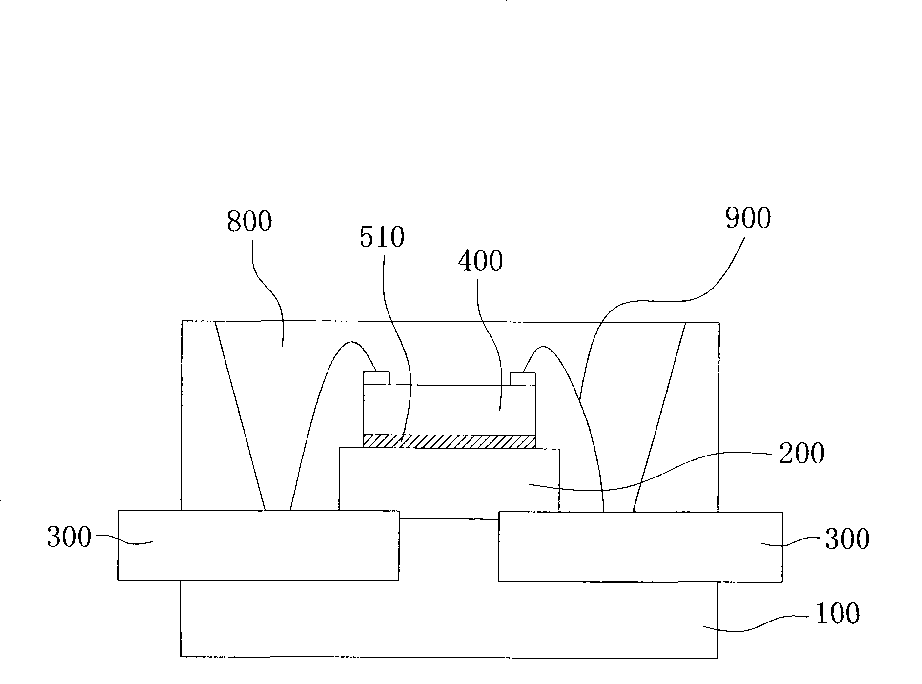
[0032] Please refer to figure 1 , is a schematic structural diagram of the light emitting diode device according to the first embodiment of the present invention. The light emitting diode device of this embodiment includes a base 100 , a substrate 200 , a bracket 300 , an LED chip 400 , a first mixed glue 510 and a packaging glue body 800 .

[0033] The substrate 200 and the bracket 300 are disposed on the base 100 , and the first mixed colloid 510 is coated between the substrate 200 and the LED chip 400 to fix the LED chip 400 on the substrate 200 . The LED chip 400 is connected to the bracket 300 by a wire 900 for conducting power to make the LED chip 400 emit light upward (FaceUp). The packaging glue body 800 is poured into the base 100 to cover the substrate 200 , the LED chip 400 and the wire 900 .

[0034] The first m...


PUM

PropertyMeasurementUnit
refractive indexaaaaaaaaaa

Abstract

An LED device includes a base, a base plate, a support, an LED chip, a first mixed colloid and a second mixed colloid, wherein the first mixed colloid and the second mixed colloid include colloid materials and insulating and heat-conducting materials; the heat-conducting materials include diamond powder, diamond-like powder or ceramic powder; the base plate and the support are arranged on the base; the first mixed colloid is applied between the base plate and the LED chip, so as to adhere and fix the LED chip and enhance the heat dissipation effect; and the second mixed colloid is poured into the base so as to coat the base plate and the LED chip, reduce the difference in the refractive index and further increase the total reflection angle and the light extraction efficiency.

Description

technical field [0001] The invention relates to a light-emitting diode packaging structure, and in particular to a light-emitting diode packaging structure packaged with a new mixed colloid. Background technique [0002] Light Emitting Diode (LED) has gradually replaced traditional lighting fixtures such as incandescent bulbs and halogen lamps due to its fast response, small size, low power consumption, low heat, and long service life. Therefore, from the beginning, LED was used as the status indicator of electronic devices, developed and applied to become the backlight of liquid crystal display, and then expanded to electronic lighting and even lighting in projectors. The application of LED is still continuing with the advancement of technology. in the extension. [0003] With the gradual improvement of LED brightness and luminous efficiency, the packaging process is also facing great double challenges. In terms of heat dissipation performance, if the high heat generated ...

Claims


Application Information

Patent Timeline
Patent Type & Authority Applications(China)
IPC IPC(8): H01L33/00H01L33/48H01L33/56H01L33/64
Inventor 许晋源张嘉显黄思玮
Owner EVERLIGHT ELECTRONICS
Why Eureka
Try Eureka