LED flexible neon lamp

A neon light and flexible technology, which is applied in the direction of damage prevention measures of lighting devices, lighting devices, light sources, etc., can solve the problems of inconvenient installation and use, large power line tension, and large external dimensions, and achieve convenient installation, large lighting angle, Small form factor effect

Inactive Publication Date: 2009-02-18
张龙平
View PDF1 Cites 3 Cited by
  • Summary
  • Abstract
  • Description
  • Claims
  • Application Information

AI Technical Summary

Problems solved by technology

complicated process
[0005] 2. The bottom of the LED lamp body is square and opaque, and the top is oval. Its disadvantages are: the light emitting angle of the LED is not more than 45 degrees, and the light emitting angle is small;
[0007] 4. The size of the product is large, the product is bulky, and the power cord is easily broken when it is bent.
Very inconvenient to install and use

Method used


Image

  • LED flexible neon lamp
  • LED flexible neon lamp
  • LED flexible neon lamp

Examples


Embodiment 1

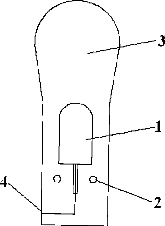
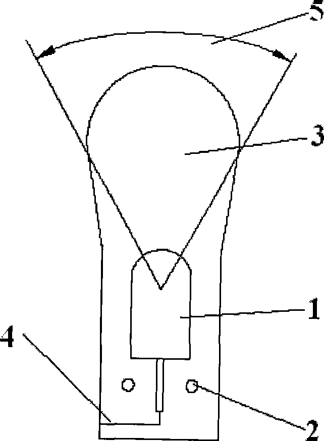
[0037] The above-mentioned LED illuminant 1 has a lateral luminous angle 6 of 70° and above 70°, and a longitudinal luminous angle 5 of 90° or less; It is upright and flat or patch-shaped.

[0038] The optimum value of the above-mentioned light-emitting angle is: the horizontal light-emitting angle is 110°; the vertical light-emitting angle is 60°.

[0039] The above-mentioned setting of the light emitting angle of the LED illuminant 1 can obtain the best effects of light emission, light mixing and light uniformity.

Embodiment 2

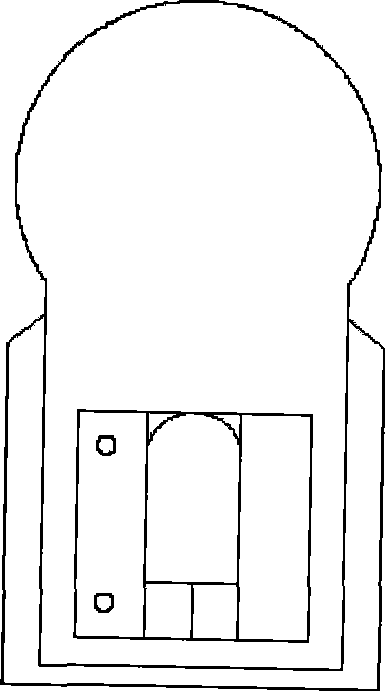
[0041] The material of the refraction light-transmitting tube body 3 described in the present invention is colored or colorless or a flexible colloid of the same color as LED light, and any one of light scattering agent, light guide powder, and phosphor powder, or any few of them, are added inside. combination of species.

[0042] The material of the above-mentioned refraction light-transmitting tube body 3 can also be a composite material of PE and PVC with different refractive indices, which is light-transmitting milky white, or the same color as the illuminant; spraying on its inner surface or outer surface or inside and outside The surface is sprayed with astigmatism agent titanium dioxide, or fluorescent powder, or acrylic powder, or fine glass beads, or any combination of the above materials, or other additives with astigmatism effect; Film 10.

[0043] Use PE or PVC with different outer skin refractive index with curved special-shaped tube, add astigmatism and laser ag...

Embodiment 3

[0045] The outer surface of the refraction light-transmitting tube body 3 at the bottom of the LED illuminant 1 described in the present invention is coated with reflective ink. Or install additional track tracks to fix, and block excess light, making it similar to the luminous effect of traditional neon lights.

[0046] The function of the reflective ink is to deflect excess light back and try to emit light from above to improve the overall luminous effect of LED flexible neon lights. For the beauty of the product, reflective ink can be coated on the side and bottom of the product, so that the light can only be emitted from the top.


PUM


Abstract

The invention discloses a LED flexible neon light; wherein, LED lighting bodies (1) are serially connected to be connected with a power supply conductor (2) in parallel; an opening (4) is correspondingly arranged on a refraction light-transmission tube body (3) in which the LED lighting bodies (1) are arranged; the LED lighting bodies (1) are pushed into the refraction light-transmission tube body (3) through the opening (4); and then the opening (4) is closed. The technical proposal is adopted to sufficiently utilize the directional lighting characteristic of the LED to vertically enlarge the lighting angle of the lighting body, so as to enable the dense lighting bodies to have linear lighting finally. The LED flexible neon light has the advantages of good flexibility, easy bending, having no need of drilling holes during the machining, convenient assembly, utilizing the material effectively, convenient mounting, being similar to the neon light in shape and lighting effect, simple structure and process, having better even illumination effect compared with the flexible neon tube in the prior art, large lighting angle, small outline dimension and saving cost.

Description

technical field [0001] The invention belongs to the technical field of indoor and outdoor decorative electric light sources, and relates to the technology of flexible neon lights. More specifically, the invention relates to an LED flexible neon light. Background technique [0002] Traditional neon lights have the advantages of uniform, continuous, high brightness, etc., but there are also disadvantages such as fragile, easy to damage, unsafe high pressure, and inconvenient replacement. In particular, professional and technical personnel must use professional equipment when replacing. Drawings can only be replaced, which is very inconvenient to use. Therefore, many neon light projects are damaged after a short period of use, and the maintenance cost is high. Therefore, there are many dead lights in neon light projects, which are very common and affect the effect of the project. [0003] The brightness of the existing LED light sources is getting higher and higher, which has ...

Claims


Application Information

Patent Timeline
IPC IPC(8): F21S4/00F21V15/02F21V23/00F21Y101/02F21S4/10F21Y115/10
Inventor 张龙平
Owner 张龙平
Why Eureka
Try Eureka