Ballast of electronic resonance fluorescent lamp

A technology for fluorescent lamps and ballasts, which is applied in the field of electronic resonance fluorescent lamp ballasts, can solve problems such as limited service life, and achieve the effects of simple structure, convenient use, and energy saving

Inactive Publication Date: 2009-02-18
陈炳桂
View PDF0 Cites 8 Cited by
  • Summary
  • Abstract
  • Description
  • Claims
  • Application Information

AI Technical Summary

Problems solved by technology

Therefore, a certain power consumption energy is generated, and the service life is also limited (generally 3-5 thousand hours)

Method used


Image

  • Ballast of electronic resonance fluorescent lamp
  • Ballast of electronic resonance fluorescent lamp
  • Ballast of electronic resonance fluorescent lamp

Examples


Embodiment Construction

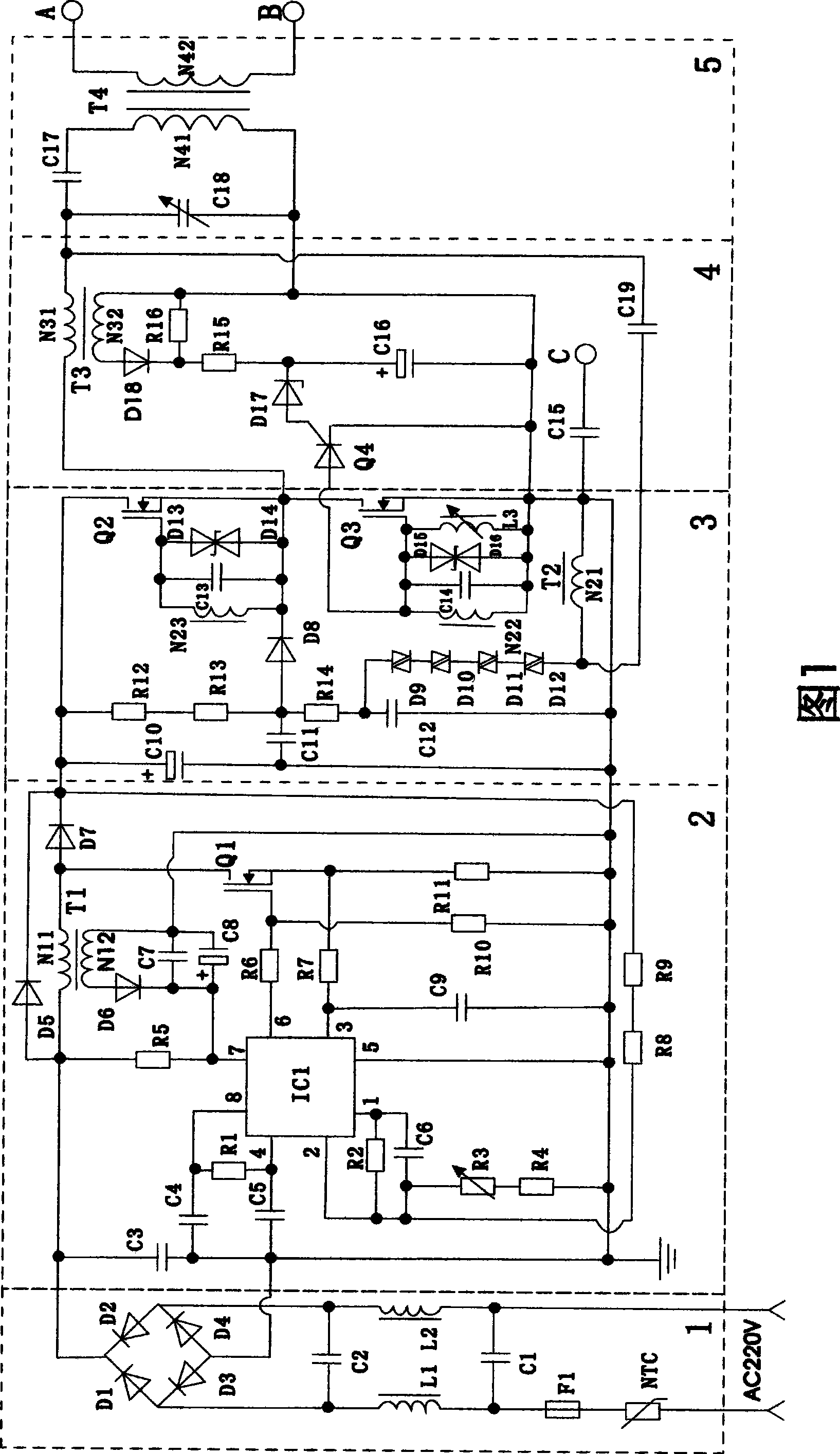
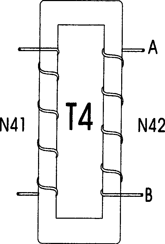
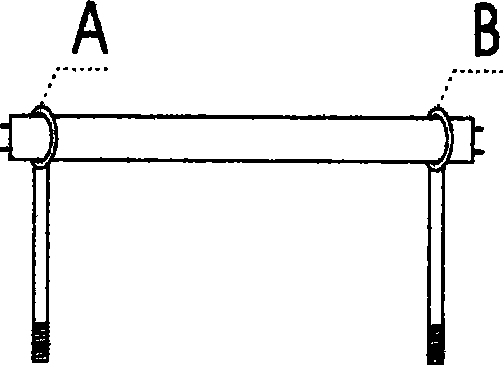
[0014] Figure 1, figure 2 , image 3 , Figure 4 As shown, the present invention includes an electronic circuit (1-4) and a resonant energy reactor circuit (5). The resonant energy reactor circuit also includes the same two or more non-magnetic metal tube snares image 3 , Figure 4 , the electronic circuit is mainly composed of a power filter DC circuit (1), a power factor correction circuit (2), a tuned oscillation amplification output circuit (3), an abnormal protection circuit (4) and a resonance energy reactor circuit (5); The resonant energy reactor is a non-magnetic metal wound on a rectangular high-magnetic body at a certain distance figure 2 , the rectangular high-magnetic body is the load of the tuned oscillation amplifying output circuit.

[0015] The electronic circuit shown in Figure 1 is a power filter DC circuit (1), a power filter network composed of inductors (L1, L2) and capacitors (C1, C2), whose function is to suppress electromagnetic interference from...


PUM


Abstract

The invention discloses a electronic resonance fluorescent lamp blast for providing a high magnetic field intensity which can make inertia gas in fluorescent lamp tube excite fluorescent powder in physical resonance under electronic energy, and combines independent gas and fluorescent powder molecular group to instantly produce brightness. It is characterized as air-tight lamp tube, no need for lamp filament and infinite lamp tube life span. The invention comprises electronic circuit and resonance reactor circuit mainly composed of energy supply filtering direct current circuit 1, power factor calibrating circuit 2, tuned oscillation amplifying circuit 3, abnormity protective circuit4 and resonance reactor circuit 5.The inventive electronic resonance fluorescent lamp blast can simultaneously ignite several lamps under high intensity energy conversion, save 80-90145404040f electricity; and can be produced in large scale and widely used in mining, home, traffic, national defence, medical care etc., especially high altitude space difficult for replacing lamp tube such as outdoor advertisement board and metro.

Description

technical field [0001] The invention relates to an electronic resonance fluorescent lamp ballast. Background technique [0002] At present, in domestic and foreign markets, industrial and agricultural production, national defense construction, medical care, transportation and other fields are inseparable from lighting sources. Fluorescent lamps have been the most widely used in lighting applications for decades. Fluorescent lamp tubes currently need to be preheated with a filament to emit light; because the filament needs a certain current to be co-heated to emit electrons and then activate the phosphor to generate energy to emit light through an inert gas. Therefore, a certain power consumption energy is generated, and the service life is also limited (generally 3-5 thousand hours). In today's world, the whole world is advocating energy saving, emission reduction, and green environmental protection. Energy-saving products such as solar lamps, energy-saving lamps, and elec...

Claims


Application Information

Patent Timeline
Patent Type & Authority Applications(China)
IPC IPC(8): H05B41/298
Inventor 陈炳桂
Owner 陈炳桂
Why Eureka
Try Eureka