
Optical isolator

An optical isolator and phase shifter technology, which is applied in the directions of instruments, optics, light guides, etc., to achieve the effect of increasing the refractive index, shortening the length of the device, and reducing the radius of curvature

Inactive Publication Date: 2009-02-25
TOKYO INST OF TECH +1
View PDF0 Cites 10 Cited by
  • Summary
  • Abstract
  • Description
  • Claims
  • Application Information

AI Technical Summary

Problems solved by technology

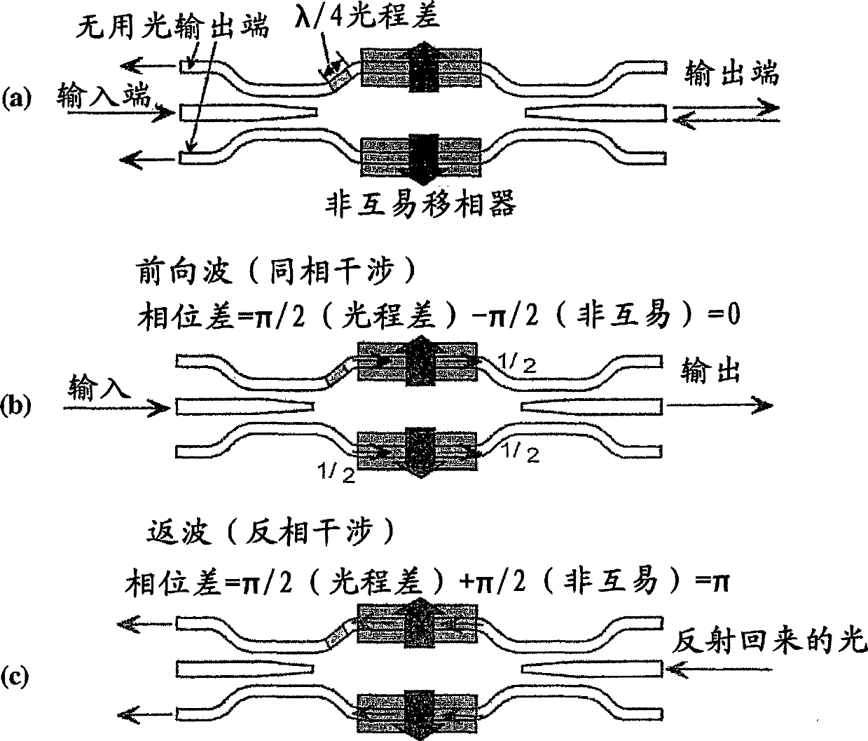
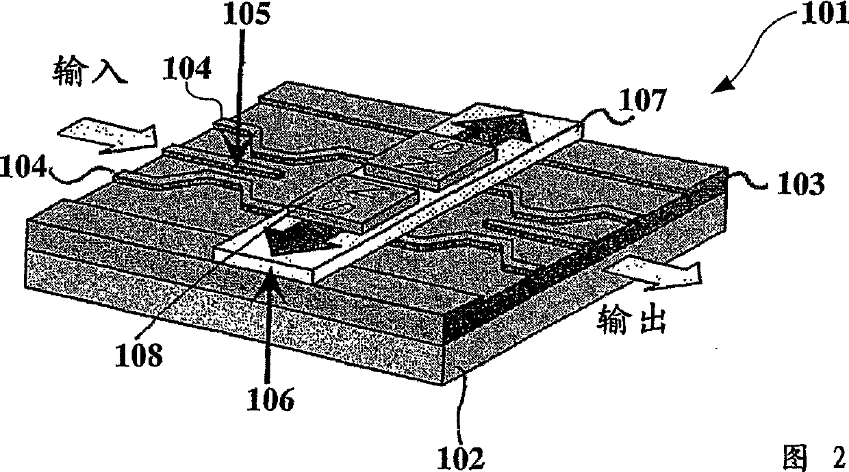
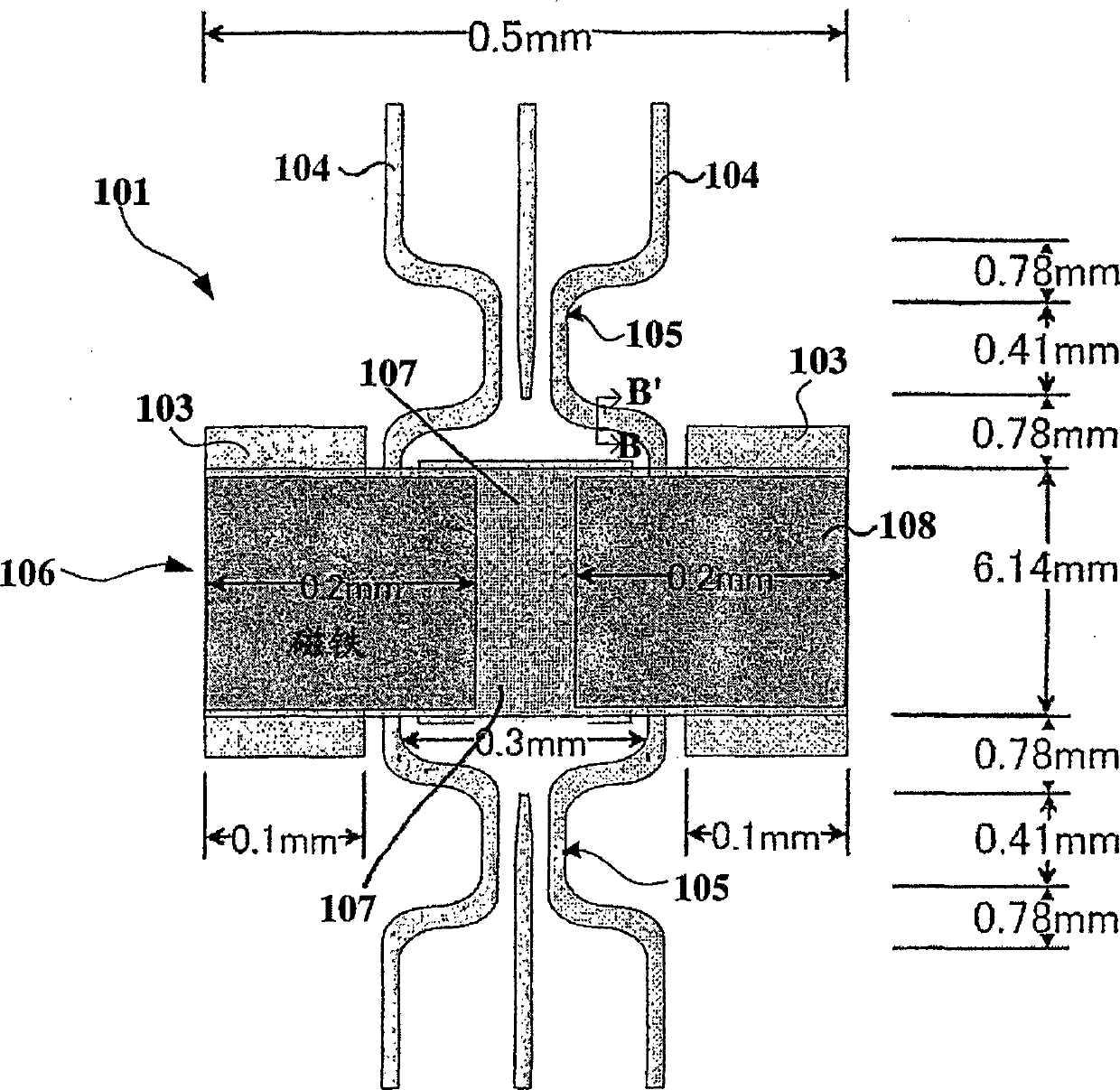
[0020] However, in the conventional optical isolator having the above-mentioned structure, the length in the direction (lateral direction) perpendicular to the light propagation direction is several to several tens of times (several μm to 100 μm) the width of the waveguide path (several μm). There is no big problem, but the element length (element length along the light transmission direction) becomes millimeter level, which is a big problem for the miniaturization of optical integrated circuits

Method used


Image

  • Optical isolator
  • Optical isolator
  • Optical isolator

Examples


Embodiment Construction

[0062] Hereinafter, the optical isolator according to the present invention will be described in detail with reference to the accompanying drawings.

[0063] [Optical isolator]

[0064] FIG. 5 is a plan view showing an example of the optical isolator 1 according to the present invention, and corresponds to the conventional optical isolator 101 of FIG. 3 . FIG. 6 is a cross-sectional view taken along the line A-A' in FIG. 5, and is a schematic cross-sectional view of the optical isolator 1. As shown in FIG.

[0065] The optical isolator 1, as shown in the figure, has a substrate 2, a waveguide layer 3, and a non-reciprocal phase shifter 4; in the waveguide layer 3, a waveguide path 5 and a curved waveguide path 6 for guiding waves in the waveguide layer 3 are formed, and further A branch coupler 7 is provided. That is, the structure of the optical isolator 1 is as follows: on the substrate 2, there is provided a semiconductor material, lattice-matched to the substrate 2, form...


PUM


Abstract

An optical isolator is constituted by providing a substrate, a waveguiding layer lattice-matched to the substrate, and a non-reciprocal phase shifter, and a waveguide and a curved waveguide for guiding the waveguiding layer are formed in the waveguiding layer, and a branch coupler is also provided therein, furthermore, a refractive index of the waveguiding layer is made larger than 3.36 by changing a semiconductor composition.

Description

technical field [0001] The present invention relates to an optical isolator with a miniaturized structure, and more particularly to changing the semiconductor composition of the waveguide layer lattice-matched to the substrate to increase the refractive index while reducing the allowable radius of curvature of the curved waveguide path, using a multimode interference type branch coupler Optical isolator with miniaturized structure to shorten the length of the device. Background technique [0002] An optical isolator is an element that allows light to pass in only one direction and blocks light traveling in the opposite direction. For example, after an optical isolator is provided at the output end of a semiconductor laser, light emitted from the laser passes through the optical isolator and can be used as a light source for optical fiber communication. Conversely, light to be incident on the semiconductor laser through the optical isolator is blocked by the optical isolator...

Claims


Application Information

Patent Timeline
Patent Type & Authority Applications(China)
IPC IPC(8): G02B27/28G02B6/12
CPCG02F1/0955G02B6/2813G02B6/125G02B6/12004G02B2006/12157G02B6/131G02F1/2257G02F2001/217G02F1/217G02B6/12
Inventor 水本哲弥樱井一正
Owner TOKYO INST OF TECH
Learn More