Deflectable micro-mechanical system and use thereof

A micro-mechanical system and deflection element technology, which is applied in the measurement of the property force of piezoresistive materials, the use of electric/magnetic devices to transmit sensing components, measurement devices, etc. Cost and other issues, to achieve the effect of improving measurement sensitivity and reducing manufacturing costs

Active Publication Date: 2009-03-04
FRAUNHOFER GESELLSCHAFT ZUR FOERDERUNG DER ANGEWANDTEN FORSCHUNG EV
View PDF2 Cites 7 Cited by
  • Summary
  • Abstract
  • Description
  • Claims
  • Application Information

AI Technical Summary

Problems solved by technology

[0012] In this case, however, the mechanical properties should not be affected, which can only be achieved with great expense or only with restrictions
In addition, significantly increased production costs

Method used


Image

  • Deflectable micro-mechanical system and use thereof
  • Deflectable micro-mechanical system and use thereof
  • Deflectable micro-mechanical system and use thereof

Examples


Embodiment Construction

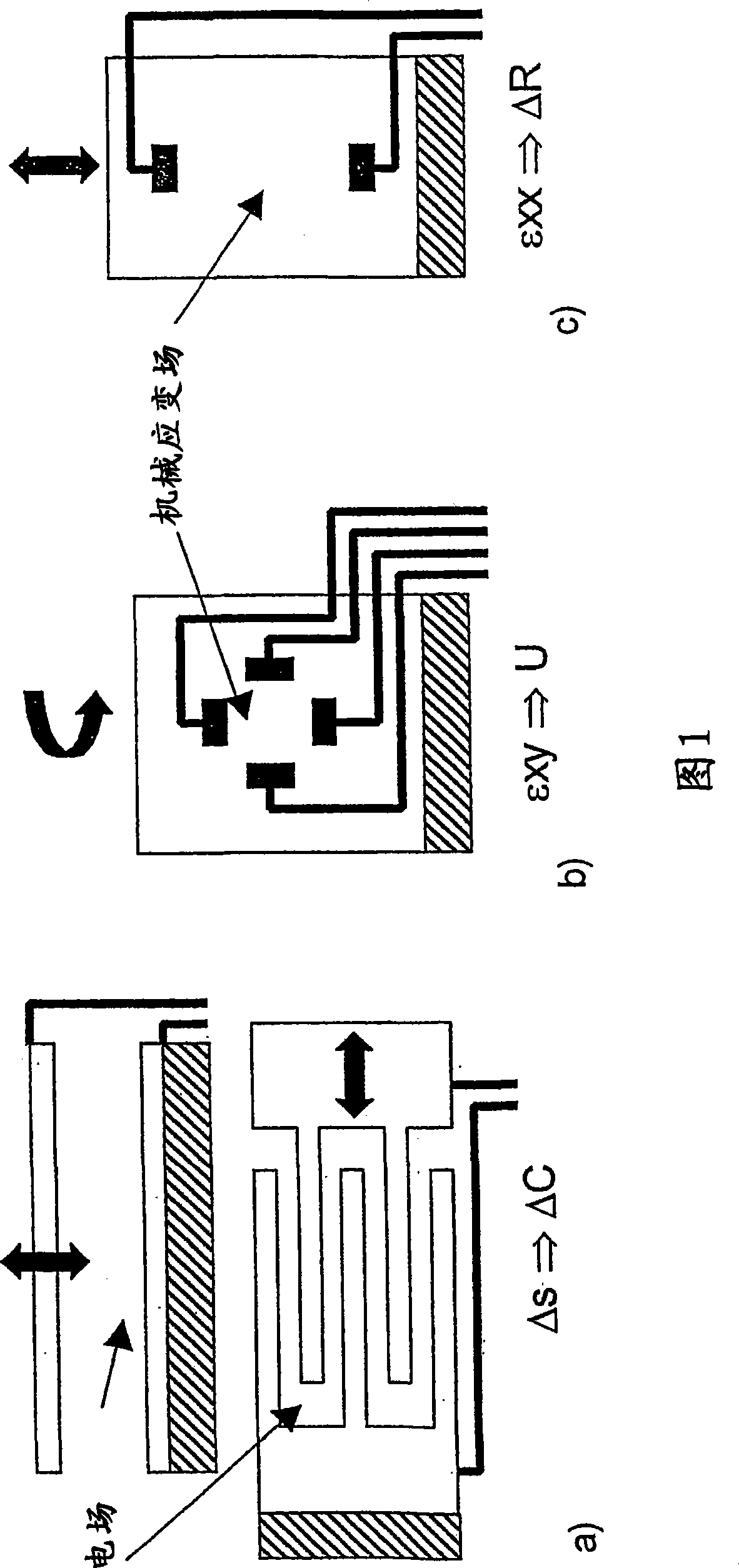
[0046] In FIG. 1 are shown the three effective principles already mentioned, for example, in the introduction to the description. In this respect, FIG. 1 a ) relates to a capacitive system; FIG. 1 b ) relates to a pseudo-Hall sensor; and FIG. 1 c ) relates to a known piezoresistive sensor.

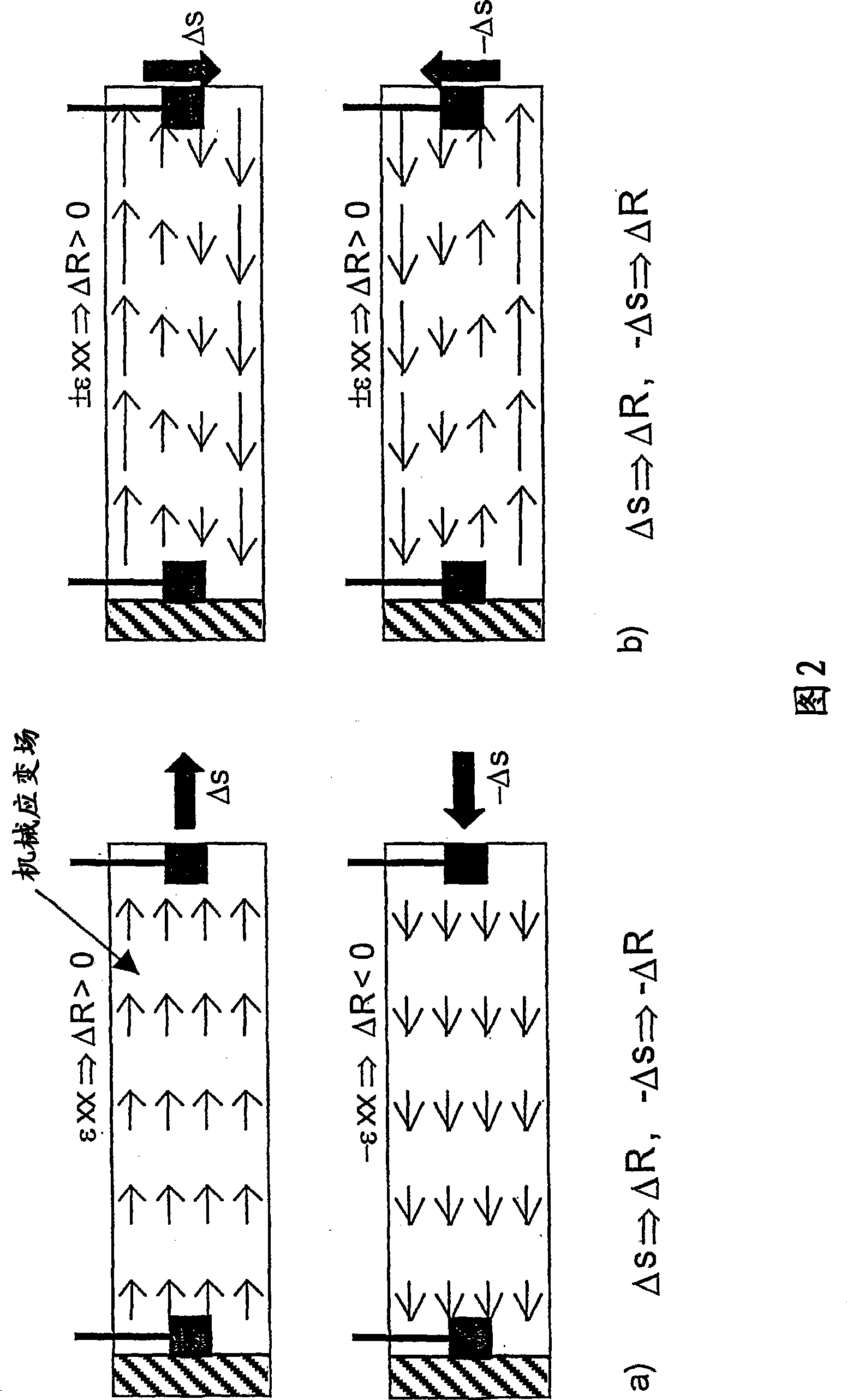
[0047] Figure 2a) shows the piezoresistive resistance change that can be detected under effective tensile force (shown in the upper part) and compressive force (shown in the lower part). FIG. 2 b ) shows the detectable piezoresistive resistance change for bending strain in different bending directions.

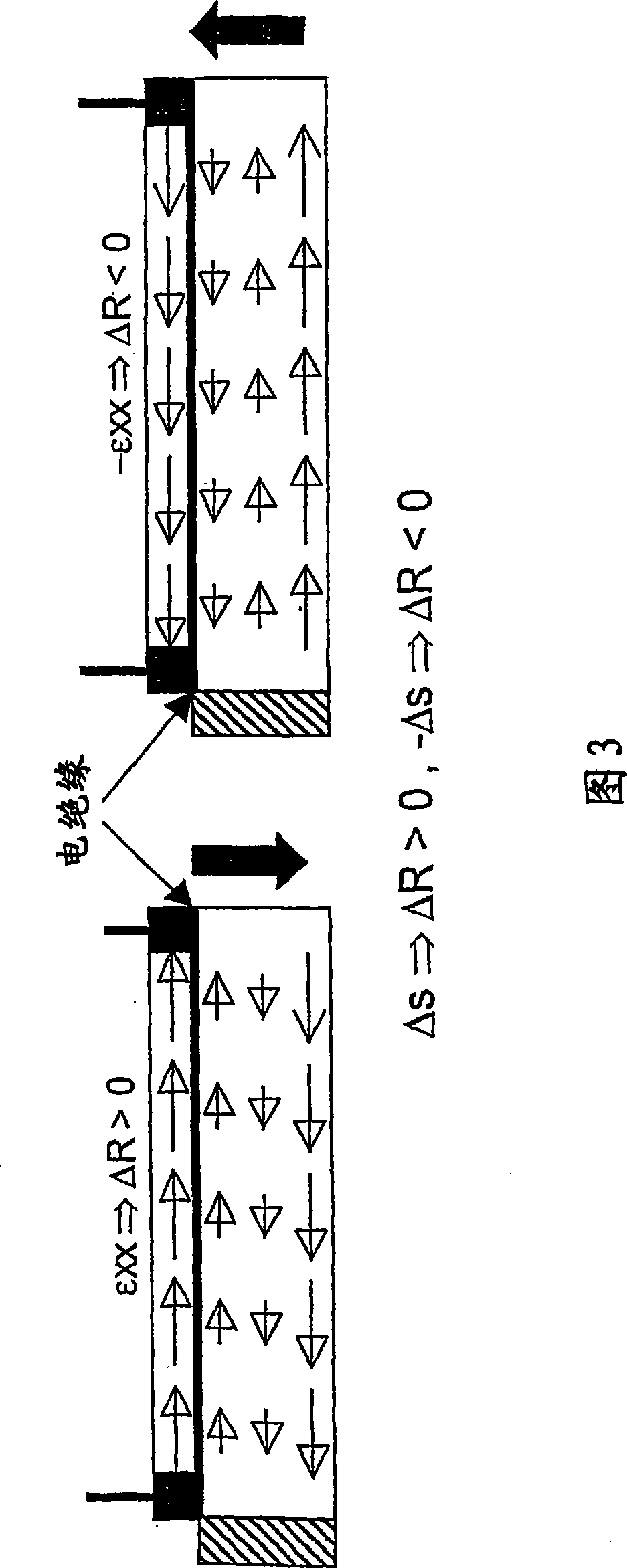
[0048] Similar to Fig. 2b), also in the case of bending with different directions, Fig. 3 shows a known possibility for observing an asymmetric relationship, in which case it can be obtained by having a quadratic part, a linear part and The constant part of the quadratic equation is used to approximate the ratio of the local resistance change to the total resistance change.

[0049] In t...


PUM


Abstract

The invention relates to deflectable micromechanical systems in which the deflection of at least one deflectable element can be determined, as well as the use thereof. According to the invention, a deflectable element is retained by means of at least one spring element while at least one unit is provided that detects the deflection. Said unit is configured as a piezoresistive sensor comprising at least two contacts which are disposed at a distance from each other in a zone that is deformed during the deflection. The contacts are connected to a voltage source. A non-homogeneous electric field is formed in a downward direction, perpendicular to contact surfaces, such that the electric resistance between contacts, which changes in accordance with the deflection, can be detected as a measure for the position. The zone that is deformed is made of electrically conducting or semiconducting material.

Description

technical field [0001] The invention relates to a deflectable micromechanical system, in which individual deflections of at least one deflectable element can be determined. This can be determined as a translational deflection and / or a rotational deflection about at least one axis of such an element. Individual position coordinates or individual deflection angles of the deflectable elements can thus be determined. Via the values ​​that can be determined in this way, other measured values ​​can be determined or the system, in particular the deflection of the element, can be effectively influenced. For example, the deflectable element may be an optical element, especially a reflective element, but also an elastically deformable element, especially a membrane. Background technique [0002] The deflection can be vibrating (can be done vibrating) and can also be done simultaneously while observing resonance. These situations can be better observed in the operation of the invent...

Claims


Application Information

Patent Timeline
Patent Type & Authority Applications(China)
IPC IPC(8): G01L1/18G01D5/16G01L9/00
CPCG01L9/0055G01L9/0002G01L1/18
Inventor 霍尔格·康拉德托马斯·克洛泽蒂洛·桑德纳
Owner FRAUNHOFER GESELLSCHAFT ZUR FOERDERUNG DER ANGEWANDTEN FORSCHUNG EV
Why Eureka
Try Eureka