Torque sensor and measuring system

A torque sensor and stress sensor technology, applied in the field of sensors, can solve the problems of multi-material, inability to realize real-time detection of mechanical equipment, long time required for installation and debugging, etc.

Inactive Publication Date: 2009-03-11
北京新宇航测控科技股份有限公司 +1
View PDF0 Cites 10 Cited by
  • Summary
  • Abstract
  • Description
  • Claims
  • Application Information

AI Technical Summary

Problems solved by technology

[0003] At present, there are shaft extensions at both ends of the torque sensor in the prior art, and the shaft extension is relatively long, accounting for about 1/2-1/3 of the total length, and a coupling is installed on the shaft extension, so the volume of the entire torque sensor The weight and weight are relatively large, not only consume more materials during manufacture, but also cannot be installed in many occasions because there is not enough space, and it is impossible to realize real-time detection of some mechanical equipment
The housing of the torque sensor in the prior art is supported and connected to the torque sensor through bearings. Since the use of the bearing has a certain limit on the rotational speed range of the rotating shaft, the range of the rotating shaft rotational speed measured by the torque sensor is also limited.
When using the torque sensor in the prior art, the center of the rotating shaft of the torque sensor and the rotating shaft of the power equipment or load to be measured must be consistent, and the installation accuracy m

Method used


Image

  • Torque sensor and measuring system
  • Torque sensor and measuring system
  • Torque sensor and measuring system

Examples


Example Embodiment

[0025] Embodiment 2 of the measurement system of the torque sensor

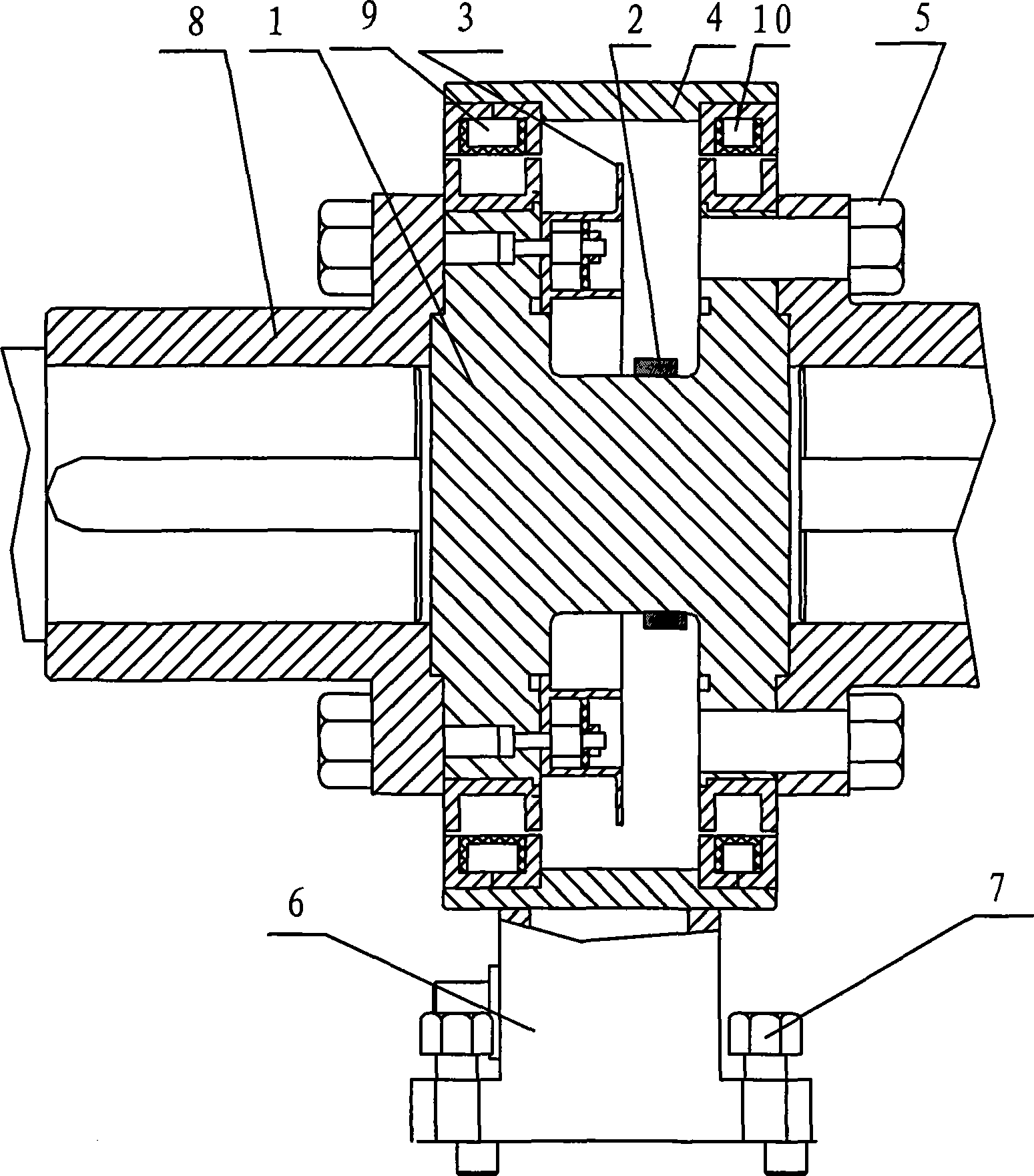
[0026] The signal coupling transformer in the first embodiment of the torque sensor measurement system can be replaced by an optical coupling signal transmission device, and the contactless transmission output of the torque measurement signal can also be realized. The specific working process is: the voltage signal output by the bridge undergoes signal processing. After the circuit is processed, it is converted into a measurable voltage frequency signal, which will be transmitted to the optical coupling signal transmission device for coupling, and converted into a measurable optical frequency signal, which can be directly output to the user's fixed receiver. The device realizes the non-contact signal transmission of the torque measurement signal, and finally obtains the torque value of the flange shaft 1.
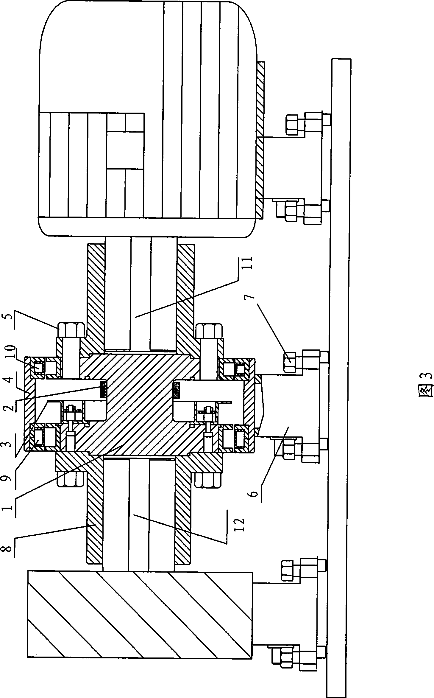
[0027] To sum up, the torque sensor of the present invention shortens the distance in the axial directi...


PUM


Abstract

The invention relates to a torque sensor which comprises a flanged shaft and a stress sensor, wherein, the two end faces of the flanged shaft are provided with ring flanges so as to be used for fixedly connecting a rotating shaft of power equipment or the rotating shaft of a load. The invention also relates to a measuring system of the torque sensor, which comprises the load, the torque sensor and the power equipment which are sequentially connected, a coupling on the torque sensor fixedly connects the rotating shaft of the power equipment and the rotating shaft of the load. By arranging the ring flanges on the end faces of the torque sensor, on the one hand, distance dimension along the axial direction is shortened, axial stability is improved, the sensor is suitable for working conditions with special dimension and is more suitable for the occasions of high speed and super high speed due to the avoidance of the use of a bearing, and the application is wider; on the other hand, the installation process is simpler and is convenient for operation.

Description

technical field [0001] The invention relates to a sensor, in particular to a torque sensor and a measuring system. Background technique [0002] In the fields of oil exploration, electric motors, railway machinery and equipment, there are many important equipment that need continuous operation. In order to obtain parameters such as torque and power of these machinery and equipment, people use torque sensors to detect the torque of the shaft of the machinery and equipment online, so as to keep abreast of the machinery and equipment The performance and working conditions of the mechanical equipment are dynamically detected and managed for real-time regulation. [0003] At present, there are shaft extensions at both ends of the torque sensor in the prior art, and the shaft extension is relatively long, accounting for about 1 / 2-1 / 3 of the total length, and a coupling is installed on the shaft extension, so the volume of the entire torque sensor The weight and weight are relativ...

Claims


Application Information

Patent Timeline
IPC IPC(8): G01L3/10G01P3/486
Inventor 张力王俊卿
Owner 北京新宇航测控科技股份有限公司
Why Eureka
Try Eureka