Semiconductor package substrate and fabrication method thereof

A technology for packaging substrates and manufacturing methods, which is applied in semiconductor/solid-state device manufacturing, semiconductor devices, semiconductor/solid-state device components, etc., and can solve the problems of reduced metal wire bonding capabilities, waste of manufacturing time, and problems with the bonding degree of wire bonding To achieve the effect of maintaining electrical quality, reducing cost and waste of time

Active Publication Date: 2009-03-11
PHOENIX PRECISION TECH CORP
View PDF0 Cites 9 Cited by
  • Summary
  • Abstract
  • Description
  • Claims
  • Application Information

AI Technical Summary

Problems solved by technology

[0007] In the existing process, if the gold formed in the bump area of ​​the electrical connection pad is too thick, there will be ion migration to the solder bump, resulting in poor surface bonding
However, if the gold is too thin in the wire bonding area, its wire bonding ability will be reduced, and a small p

Method used


Image

  • Semiconductor package substrate and fabrication method thereof
  • Semiconductor package substrate and fabrication method thereof
  • Semiconductor package substrate and fabrication method thereof

Examples


Embodiment Construction

[0040] The implementation of the present invention is described below through specific examples, and those skilled in the art can easily understand other advantages and effects of the present invention from the content disclosed in this specification. The present invention can also be implemented or applied through other different specific embodiments, and various modifications and changes can be made to the details in this specification based on different viewpoints and applications without departing from the spirit of the present invention.

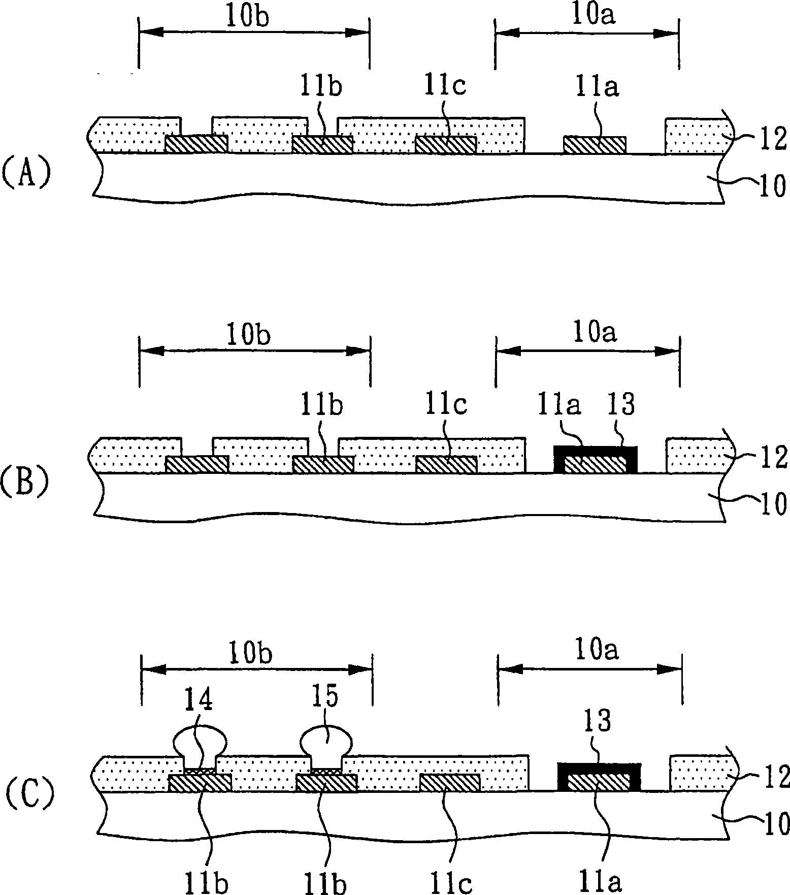
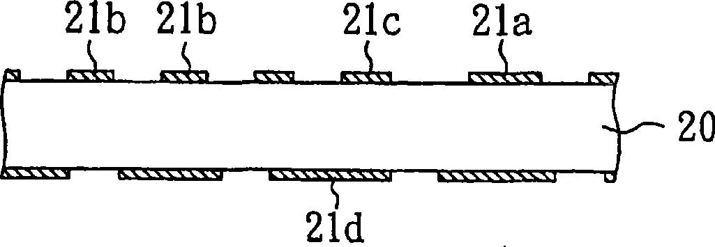
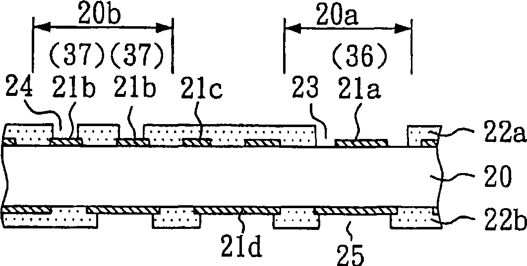
[0041] Please refer to Figures 2A to 2F , is a cross-sectional view of the manufacturing method of the semiconductor package substrate of the present invention. However, the drawings described are simplified schematic diagrams. The icons only show the components related to the present invention, and the components shown are not the actual implementation. The number and shape of the components in the actual implementation are a selecti...


PUM


Abstract

The invention relates to a semiconductor packaging substrate and a fabricating method thereof. The invention is characterized in that electric connection pads on the surface of a circuit board provided with a wire bonding area and a lug area synchronously form a nickel/palladium/metal layer, so as to reduce the flow of process and the waste of time. The effect for enhancing the binding force between the substrate and the chip exists in the nickel/palladium/metal layer.

Description

technical field [0001] The invention relates to a semiconductor packaging substrate and a manufacturing method thereof, in particular to a semiconductor packaging substrate suitable for simultaneously forming a nickel / palladium / gold layer in a wire bonding area and a bump area and a manufacturing method thereof. Background technique [0002] Due to the increasingly thinner, thinner and multi-functional requirements of electronic products, the development of integrated circuit chip packaging technology is also promoted, which in turn promotes the multi-pin and thinner chip packaging. [0003] In order to adapt to the trend of thinner and smaller and to pursue high-density packaging, Ball Grid Array, Chip Scale Package, and Flip Chip technologies have become mainstream packaging technologies. Therefore, requirements such as small area, improved I / O (input / output) pins, wiring densification, low noise, product reliability, and even manufacturing cost have become important issue...

Claims


Application Information

Patent Timeline
IPC IPC(8): H01L23/498H01L21/48
CPCH01L2224/73204H01L2224/16225H01L2224/48091H01L2224/45147H01L2224/32225H01L2224/45144
Inventor 陈柏玮王仙寿
Owner PHOENIX PRECISION TECH CORP
Why Eureka
Try Eureka