

Projection objective magnification error and distortion detection device and method
A technology of projection objective lens and detection device, which is applied in the field of performance detection of projection optical system, and can solve problems such as inability to identify errors, affect the final performance of lithography equipment, and inability to distinguish template graphic projection objective errors, etc.
- Summary
- Abstract
- Description
- Claims
- Application Information
AI Technical Summary
Problems solved by technology
Method used
Image

Examples
Embodiment Construction
[0021] The device and method for detecting the magnification error and distortion of the projection objective lens of the present invention will be further described in detail below in conjunction with a preferred embodiment.
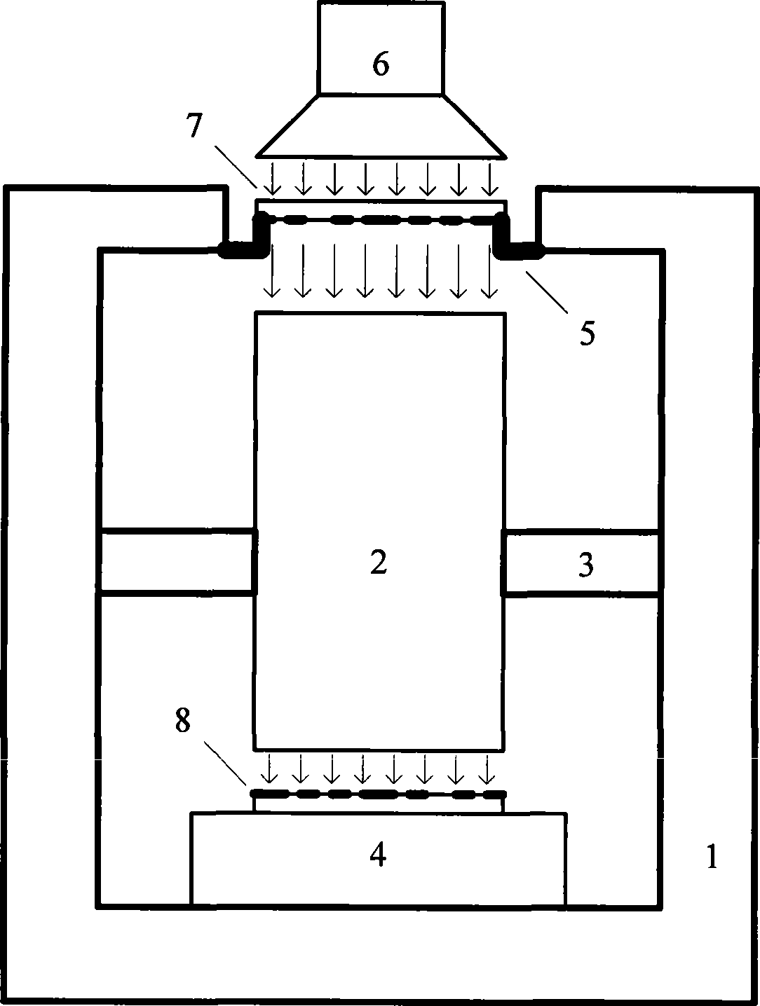
[0022] see figure 1 , is a schematic block diagram of a preferred embodiment of the projection objective lens magnification and distortion detection device of the present invention, as shown in the figure, in this embodiment, the projection objective lens magnification and distortion detection device includes a frame unit 1, a projection An objective lens 2 , a projection objective lens fixing unit 3 , a film carrier unit 4 , a plate carrier unit 5 , an illumination unit 6 , a measurement reticle 7 and a transfer reticle 8 .
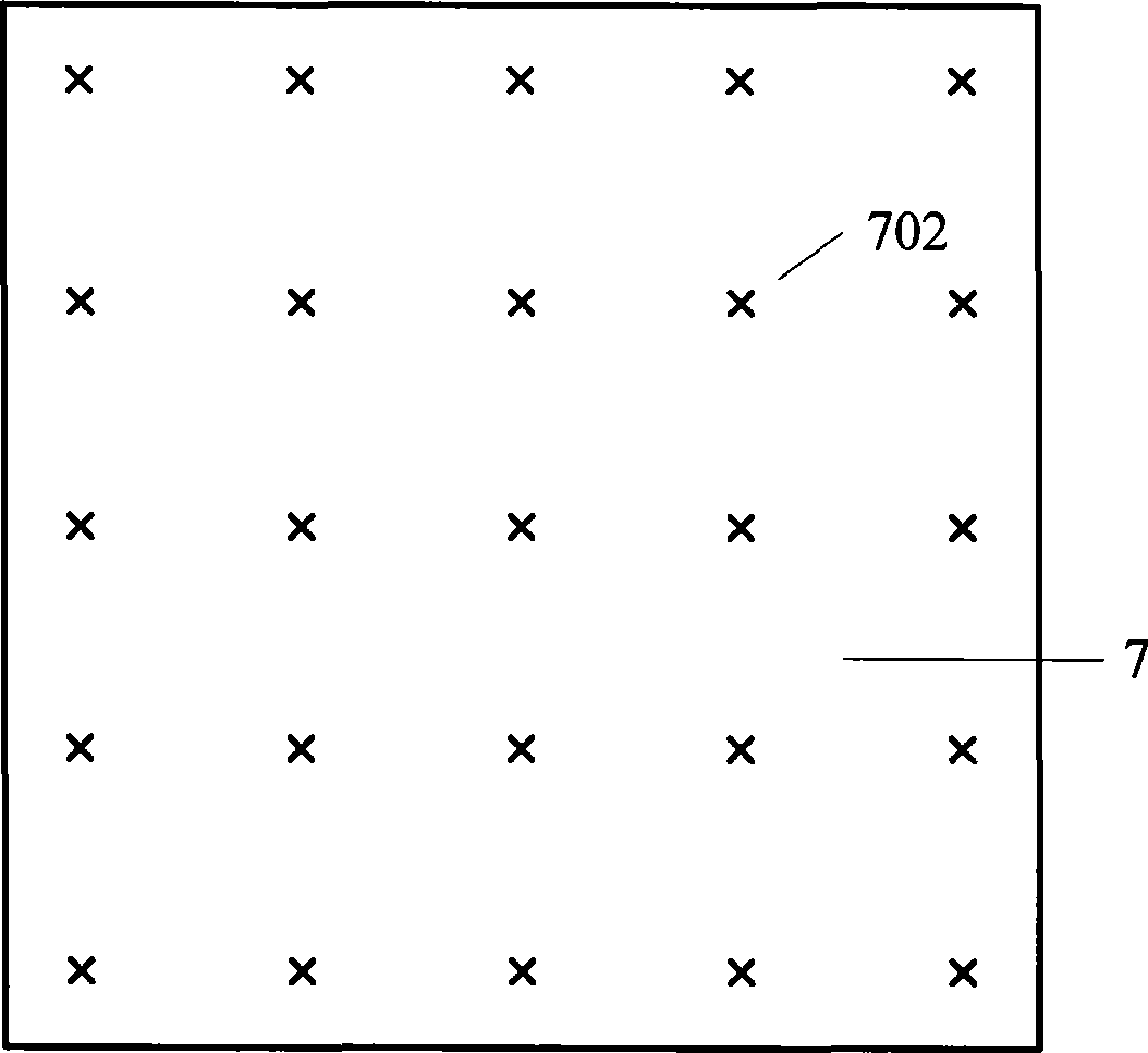
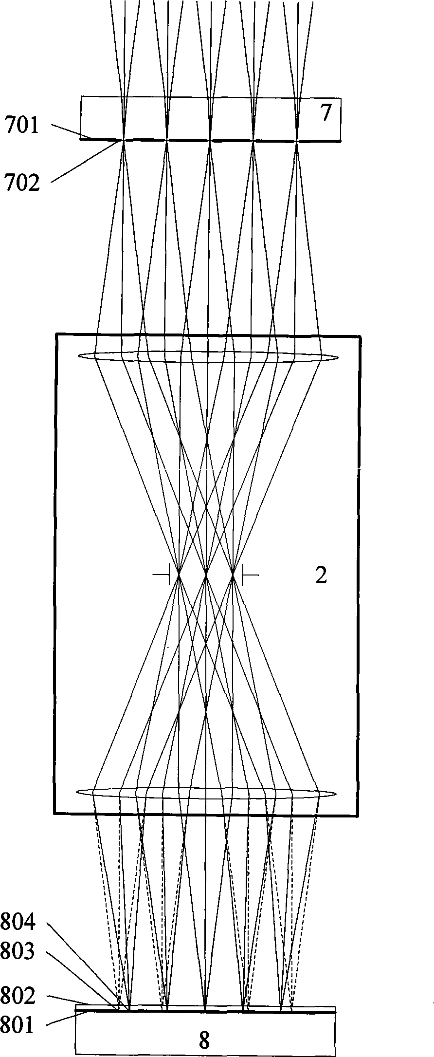
[0023] Please also see figure 2 , image 3 , the projection objective lens 2 is installed on the frame unit 1 through the projection objective lens fixing unit 3, and the chrome-plated surface 701 of the measuring reticle 7 inc...
PUM
 Abstract
Description
Claims
Application Information