Lighting unit

A lighting unit and component technology, applied in lighting devices, lighting and heating equipment, cooling/heating devices of lighting devices, etc., can solve problems such as complex, expensive, and unable to ideally realize the heat removal of halogen lamps, and achieve improvement The effect of thermal management

Inactive Publication Date: 2009-03-18
KONINKLIJKE PHILIPS ELECTRONICS NV
View PDF2 Cites 7 Cited by
  • Summary
  • Abstract
  • Description
  • Claims
  • Application Information

AI Technical Summary

Problems solved by technology

[0006] The technical problem faced by the lighting units described above is that these units comprising halogen lamps are becoming more and more expensive and complex to manufacture, and the removal of heat from the halogen lamps is not ideally achieved.

Method used


Image

  • Lighting unit
  • Lighting unit
  • Lighting unit

Examples


Embodiment Construction

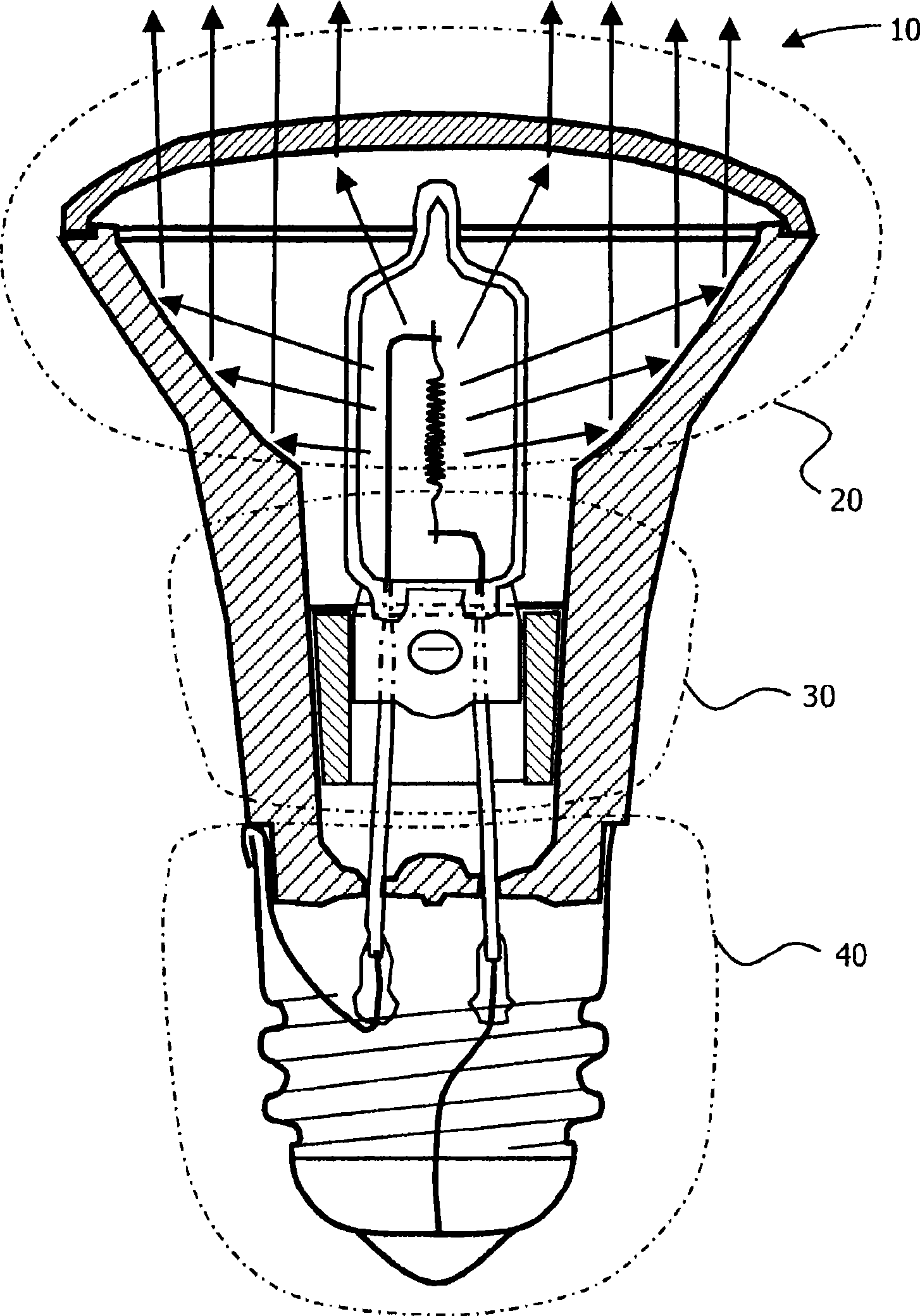
[0037] see figure 1 , an embodiment of the invention, namely a lighting unit, generally indicated at 10, is shown. The lighting unit 10 comprises a reflector portion indicated at 20 , a neck portion indicated at 30 and a base portion indicated at 40 . In operation, reflector portion 20 is an area in which optical radiation is generated, reflected and then refracted to produce an optical radiation beam. Also, in operation, the neck portion 30 provides mechanical support and also performs a cooling function. Furthermore, the base portion 40 is involved in providing an Edison screw type connection for coupling electrical power to the lighting unit 10 .

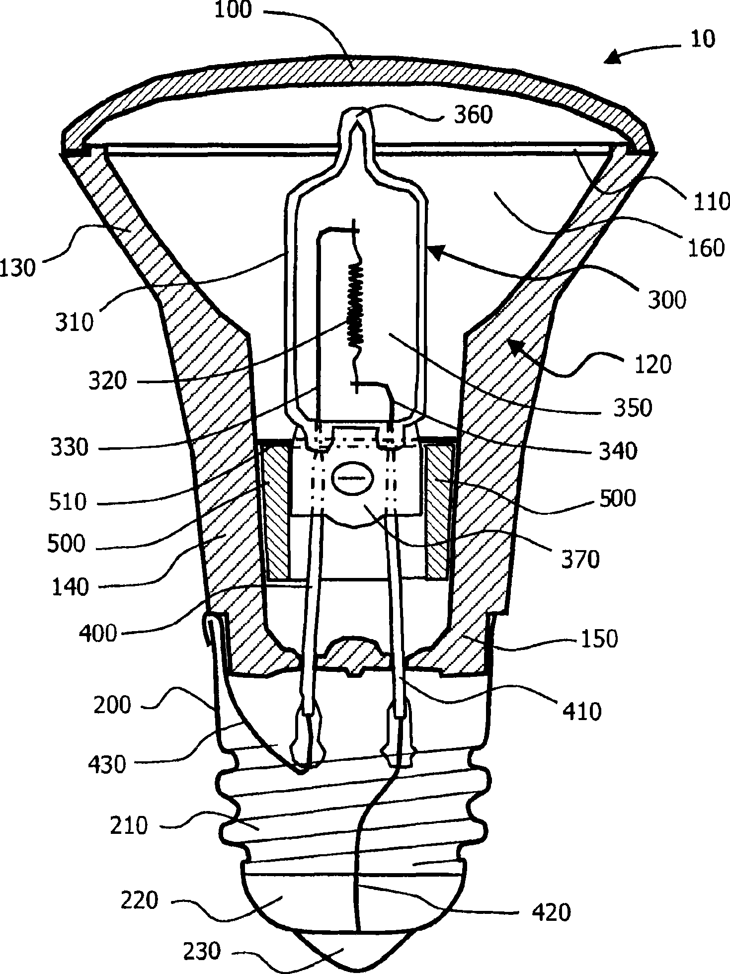
[0038] see below figure 2 , the components of the lighting unit 10 will be further described. The lighting unit 10 includes a substantially light-transmissive dome shape 100 to refract optical radiation to generate a beam of optical radiation from the unit 10 in operation; alternatively, the lens 100 is provided with a textu...


PUM


Abstract

A lighting unit (10) includes a reflector region (130) coupled to a neck region (140) coupled to a base region (150) is described. These regions (130, 140, 150) define an inner region (160) for inclusion of a lamp (300), in that the reflector region (130) can be operated to reflect radiation generated by the lamp (300), the neck region (140) is disposed at least partially to surround the lamp (300), and the base region (150) is disposed to convey electrical connections to the lamp (300). The unit (10) further includes a heat-conducting arrangement of elements (500, 510) to conduct, in operation, heat energy generated by the lamp (300) substantially to the neck region (140) for subsequent dissipation therefrom.

Description

technical field [0001] The invention relates to a lighting unit comprising a halogen lamp. The invention also relates to a method of manufacturing such a lighting unit comprising a halogen lamp. Background technique [0002] Lighting units comprising halogen lamps are generally known and are currently used in a wide range of applications where a relatively high luminous flux is required, for example in image projectors, interior lighting and automotive lighting. Halogen lamps consist of a conductive thread filament supported by electrodes within a quartz lamp envelope. The lamp envelope is sealed and internally contains a halogen gas at a relatively high pressure, such as about 6 bar. These electrodes provide the electrical connection from the area outside the lamp envelope to the filament inside the lamp envelope. [0003] In operation, an electric current is passed through the wire filament, thereby heating the wire filament to white heat. Due to heat conduction from t...

Claims


Application Information

Patent Timeline
Patent Type & Authority Applications(China)
IPC IPC(8): H01J61/52H01K1/58F21V29/00F21Y101/00
CPCH01K1/325H01K1/58
Inventor J·休扎V·M·朱拉多
Owner KONINKLIJKE PHILIPS ELECTRONICS NV
Why Eureka
Try Eureka