Production equipment special for numerical control groove drum

A technology of production equipment and groove drum, which is applied to milling machine equipment, details of milling machine equipment, metal processing equipment, etc., can solve problems such as low production efficiency, high unit cost, and expensive equipment, so as to achieve high production efficiency and improve competition The effect of high capacity and high cost of use

Inactive Publication Date: 2009-03-25
台州宇硕自络槽筒有限公司
View PDF0 Cites 9 Cited by
  • Summary
  • Abstract
  • Description
  • Claims
  • Application Information

AI Technical Summary

Problems solved by technology

[0002] The groove drum is a key accessory for winding yarn on the textile machine in the textile industry. According to the material, the groove drum can be divided into bakelite groove drum, plastic groove drum, steel plate groove drum and metal groove drum. The working principle of the metal groove drum is winding according to friction transmission. The principle is to wind the yarn. In this mechanism, a specially treated metal grooved drum is directly driven by a DC servo motor. The axis of the yarn is rotated, the groove on the surface of the winding yarn and the drum acts as a yarn guide to make the yarn evenly wound onto the surface of the bobbin. The shape of the groove determines the law of the yarn guiding movement, and different types of acceleration curves ensure that The required starting speed of the drum is controlled by the computer, and the transmission ratio between the drum and the yarn is controlled by the computer. When the yarn b

Method used


Image

  • Production equipment special for numerical control groove drum
  • Production equipment special for numerical control groove drum

Examples


Embodiment Construction

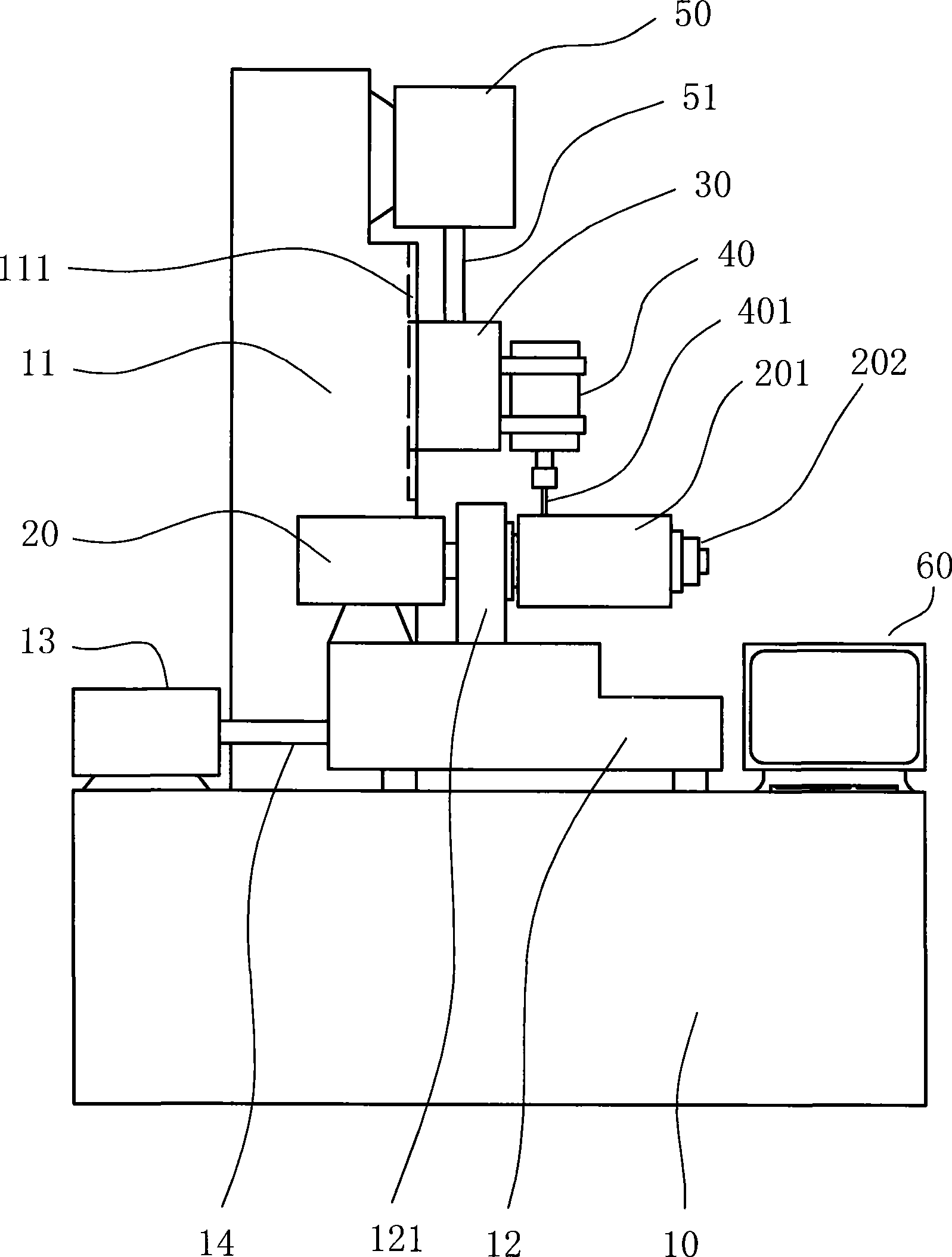
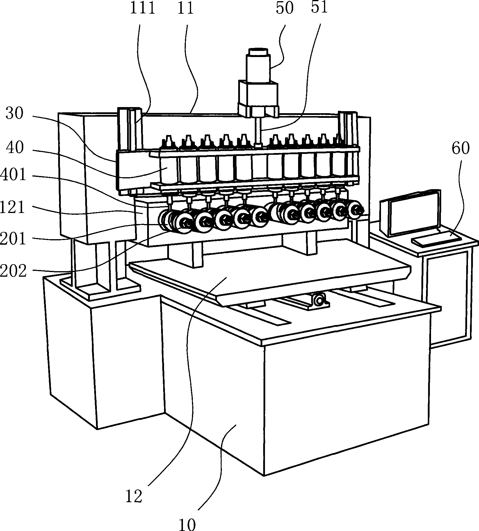
[0023] The present invention will be further described below with specific embodiment, see figure 1 -2:

[0024] The special production equipment for numerically controlled slot cylinders includes a frame 10, a motor, and a milling cutter 401. It is characterized in that: a sliding platform 12 is arranged on the frame 10, and the sliding platform 12 is driven by a motor to move left and right along the X axis and pass through the motor 13. Drive it to move back and forth along the Y axis, a grooved cylinder support 121 is arranged on the top of the sliding platform 12, and more than two grooved cylinder clamps 202 are arranged on the grooved cylinder support 121, and a grooved cylinder motor 20 drives two through a synchronous gearbox. More than two groove tube clamps 202 rotate, and the middle rear part of frame 10 is fixed with mounting frame 11, and the front portion of mounting frame 11 is provided with slideway 111, and the top is provided with elevating motor 50, is prov...


PUM


Abstract

The invention provides a special production equipment of a numerical control grooved drum, which belongs to the technique field of numerical control milling machines, wherein, a sliding platform and a transmission mechanism are arranged on a frame, a grooved drum support and more than two sets of grooved drum motors and grooved drum jigs are disposed at the upper part of the sliding platform, a mounting rack is fixed at the middle and rear part of the frame, a jacking motor, a milling cutter motor mounting rack, a milling cutter motor and a milling cutter are arranged on the mounting rack, and the movement of the invention is controlled by a controller according to the edited program and the corresponding servo motor, and the invention has the advantages that: the production efficiency of the equipment is ten times higher than the existing equipment, but the price is only one eighth of that of the existing equipment, the lifetime of the metal grooved drum manufactured by the equipment is 8 to 10 years, the winding speed is 1300m/min, and the time of not-in-place at both ends is zero, and the invention can meet the requirements of domestic production as well as new situations of energy saving, consumption reduction and emission reduction, and enhance the competitive power of the national textile industry, and the equipment is used to manufacture various cone winding machines and parallel winding machines with different angles of taper.

Description

technical field [0001] The invention relates to the technical field of numerical control milling machines, in particular to a special production equipment for numerical control grooved cylinders. Background technique [0002] The groove drum is a key accessory for winding yarn on the textile machine in the textile industry. According to the material, the groove drum can be divided into bakelite groove drum, plastic groove drum, steel plate groove drum and metal groove drum. The working principle of the metal groove drum is winding according to friction transmission. The principle is to wind the yarn. In this mechanism, a specially treated metal grooved drum is directly driven by a DC servo motor. The axis of the yarn is rotated, the groove on the surface of the winding yarn and the drum acts as a yarn guide to make the yarn evenly wound onto the surface of the bobbin. The shape of the groove determines the law of the yarn guiding movement, and different types of acceleration...

Claims


Application Information

Patent Timeline
IPC IPC(8): B23C3/34B23C1/08B23C9/00B23Q3/06B65H54/48
Inventor 林卫平
Owner 台州宇硕自络槽筒有限公司
Why Eureka
Try Eureka