
Suspended type pipe-jointing welding robot

A welding robot, hanging technology, applied in welding equipment, auxiliary welding equipment, welding/cutting auxiliary equipment, etc., can solve the problems of small working space, difficult to achieve card installation, and unfavorable real-time observation and operation of operators, and achieve welding. good quality effect

Active Publication Date: 2009-03-25
安徽行健智能制造装备股份有限公司
View PDF0 Cites 65 Cited by
  • Summary
  • Abstract
  • Description
  • Claims
  • Application Information

AI Technical Summary

Problems solved by technology

[0002] At present, the connection welding robot mostly adopts three-jaw or four-jaw chucks for clamping, and the clamping is carried out on the welded connection pipe, which is very easily transmitted to the chuck due to heat generated by welding, causing it to be stuck due to thermal deformation, making it difficult to disassemble the chuck ; In the welding with closely distributed nozzles, the welding operation space of the clamp-type welding robot is severely limited. At the same time, due to the installation method of the clamp-type welding robot, the operating space left for the operator is very small, which is not conducive to the operator's safety. Real-time observation and operation; It is difficult to realize the chucking of the pipe welding robot using the three-jaw or four-jaw chuck for the welding of the opposite pipe, oval pipe, tapered pipe and other irregular pipes, so that it is impossible to realize the chucking for welding; urgently needed in practice A robot that is easy for workers to observe and operate, can avoid the chuck from being stuck due to welding heat, and can adapt to welding of different shapes.

Method used


Image

  • Suspended type pipe-jointing welding robot
  • Suspended type pipe-jointing welding robot
  • Suspended type pipe-jointing welding robot

Examples


Embodiment Construction

[0020] The present invention is described in more detail below in conjunction with accompanying drawing example:

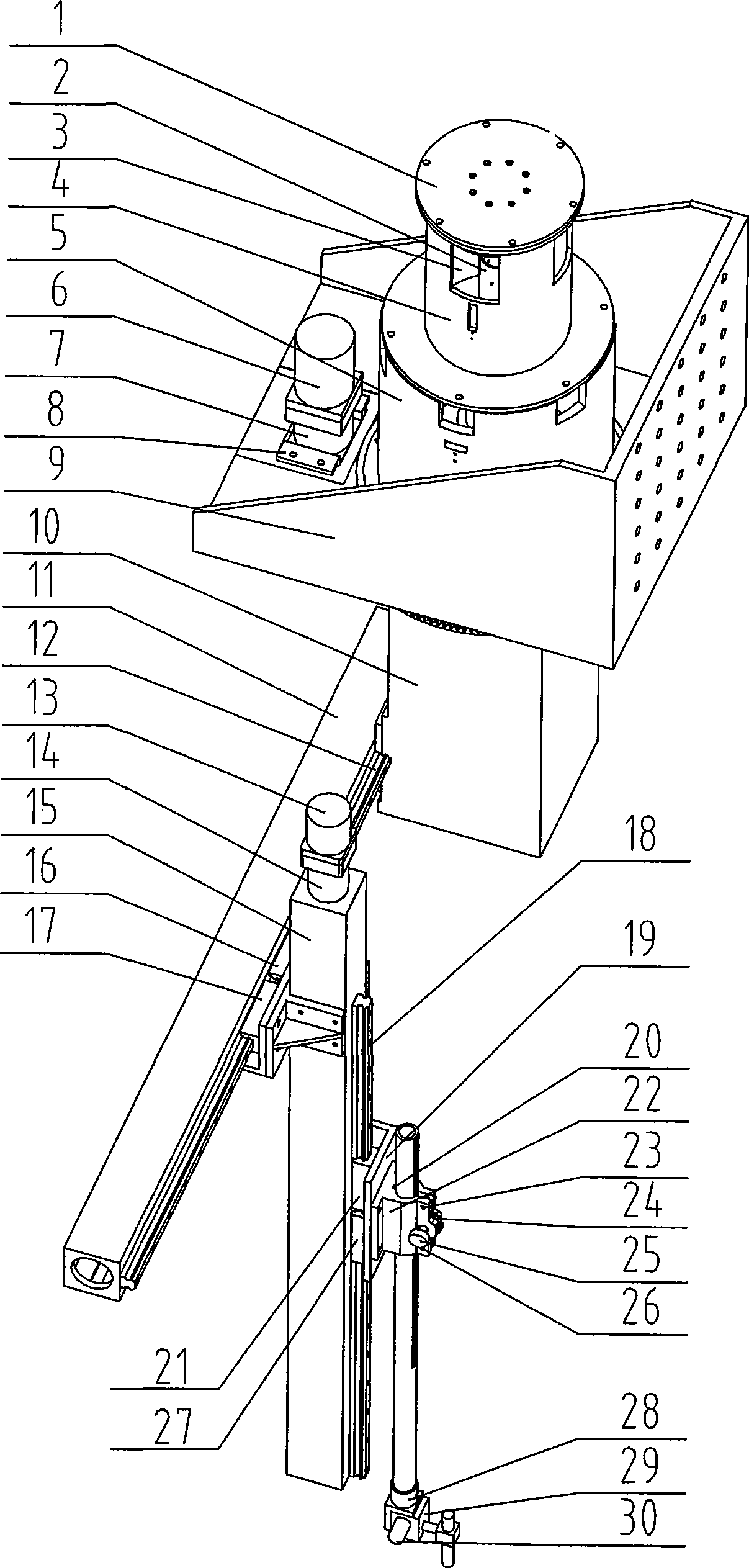
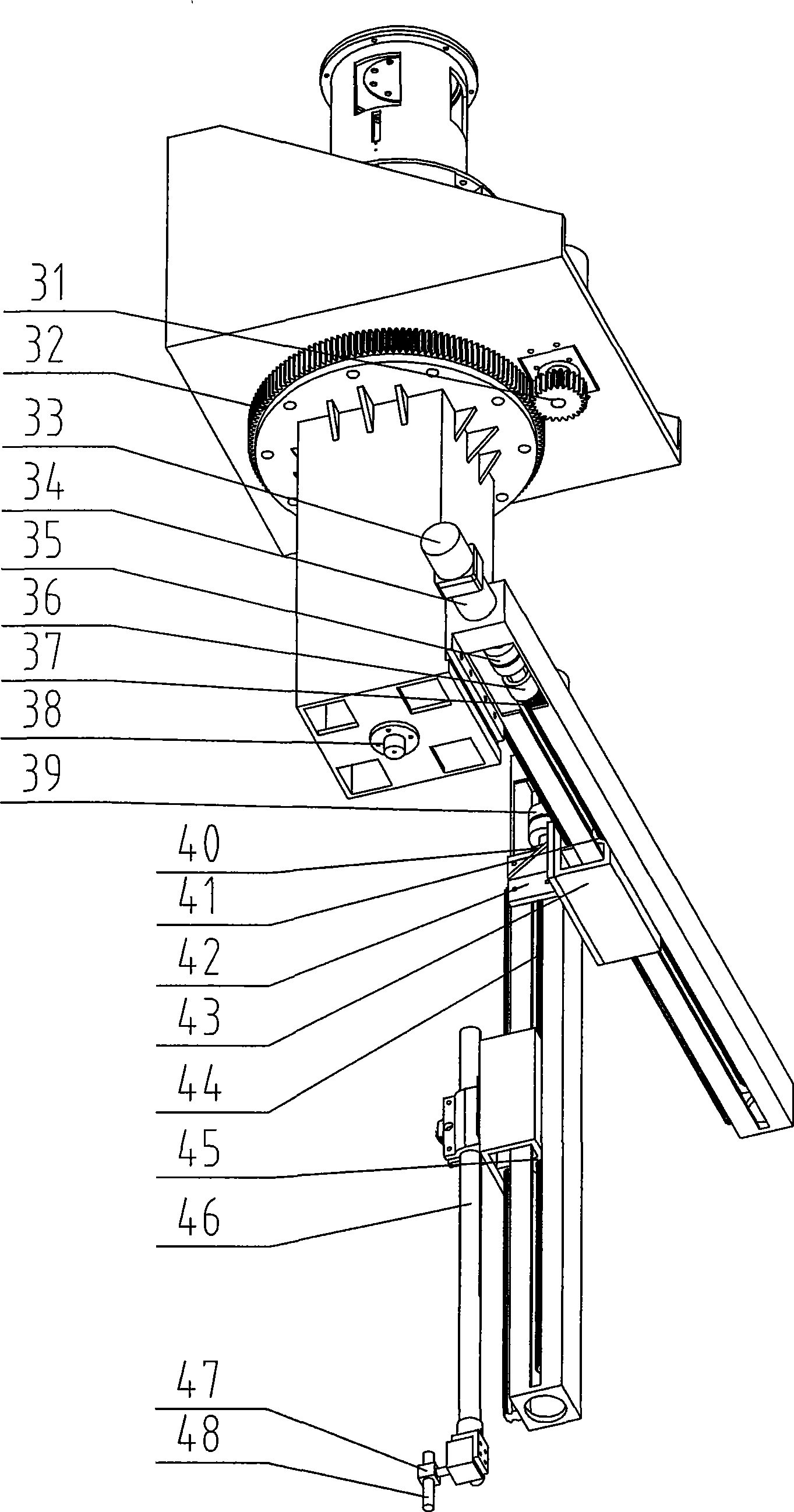
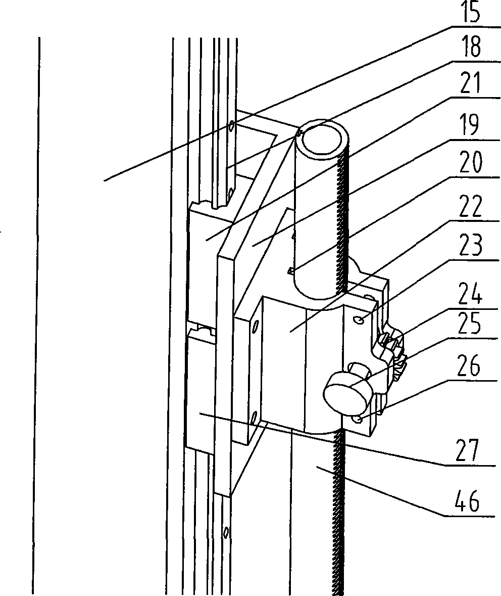
[0021] of the present invention Figure 1-Figure 6 The symbols of each part represent: 1. End cover, 2. Mandrel, 3. Circuit slip ring, 4. Shell I, 5. Shell II, 6. Servo motor, 7. Reducer, 8. Bracket, 9. Large hanger, 10. Rotating box, 11. Telescopic arm, 12. Linear slide rail, 13. Stepping motor, 14. Reducer, 15. Lifting arm, 16, 17. Slider, 18. Linear slide rail, 19. Lifting connection block, 20. Key, 21. Slider, 22. Clamper, 23, 26. Screw, 24. Lifting adjustment pinion, 25. Handwheel, 27. Slider, 28. End connecting block, 29. Worm gear reducer, 30. Stepping motor, 31. Rotating pinion, 32. Slewing ring, 33. Stepping motor, 34. Reducer, 35. Coupling, 36. Ball screw bracket, 37. Ball screw, 38. Laser, 39. Coupling, 40. Ball screw bracket, 41. Screw nut, 42. Two-arm connecting block, 43. Telescopic moving block, 44. Ball screw, 45. Lead screw Nut, 46. rack tube, ...


PUM


Abstract

The invention provides a hanging-style pipe connecting welding robot composed of an electrical sliding loop part, a rotary mechanism, a stretching mechanism, a lifting mechanism, a sewing mechanism and a manually lifting adjusting mechanism. The rotary mechanism consists of a fixed part and a rotary part. The fixed part of the rotary mechanism is fixed on the end of the horizontal arm of the cross arm as a seat of the hanging-style robot, and the stretching mechanism is arranged on the rotary part of the rotary mechanism. The lifting mechanism is arranged on the stretching mechanism, and the lifting adjusting mechanism is arranged on the lifting mechanism, the sewing mechanism is arranged on the manually lifting adjusting mechanism. The electrical sliding loop part is arranged on the rotary mechanism. By adjusting the relative position between the welding robot and the connecting pipe and adjusting the manually lifting adjusting mechanism to proper welding position, the hanging-style pipe connecting welding robot can realize linkage at four degrees of freedom, and can perform automatic welding for different shape of pipes with the advantages of good welding quality, high efficiency and reduced labor intensity of workers.

Description

(1) Technical field [0001] The invention relates to an industrial welding robot, in particular to a joint intersecting line welding robot used for cylinders, ellipsoidal caps, spherical caps and cones. (2) Background technology [0002] At present, pipe welding robots mostly use three-jaw or four-jaw chucks for clamping. When clamping on the welded pipe, the heat generated by welding is easily transmitted to the chuck, causing it to be stuck due to thermal deformation, making it difficult to disassemble the chuck. ; In the welding with tightly distributed nozzles, the welding work space of the clamp-type welding robot is severely limited. At the same time, due to the installation method of the clamp-type welding robot, the operating space left for the operator is very small, which is not conducive to the operator's safety. Real-time observation and operation; It is difficult to realize the chucking of the pipe welding robot using the three-jaw or four-jaw chuck for the weldi...

Claims


Application Information

Patent Timeline
IPC IPC(8): B23K37/00B23K37/047B25J3/04
Inventor 杜宏旺王宗义赵亚楠刘涛李燕东张浩鹏
Owner 安徽行健智能制造装备股份有限公司
Learn More