Method for producing compressor, and compressor

A manufacturing method and compressor technology, which are applied in the field of compressor manufacturing, can solve the problems of difficulty in ensuring the positional accuracy of internal components, large-scale compressors, and large heat input, and achieve the effects of suppressing deformation and reducing costs.

Inactive Publication Date: 2009-03-25
DAIKIN IND LTD
View PDF3 Cites 6 Cited by
  • Summary
  • Abstract
  • Description
  • Claims
  • Application Information

AI Technical Summary

Problems solved by technology

In a compressor with such a casing, when the conventional method of fixing the internal parts to the main body casing by arc welding is used, the amount of heat gain is too large, and it is difficult to ensure the positional accuracy of the internal parts
On the other hand, the following method can also be considered: instead of directl

Method used


Image

  • Method for producing compressor, and compressor
  • Method for producing compressor, and compressor
  • Method for producing compressor, and compressor

Examples


no. 1 Embodiment approach

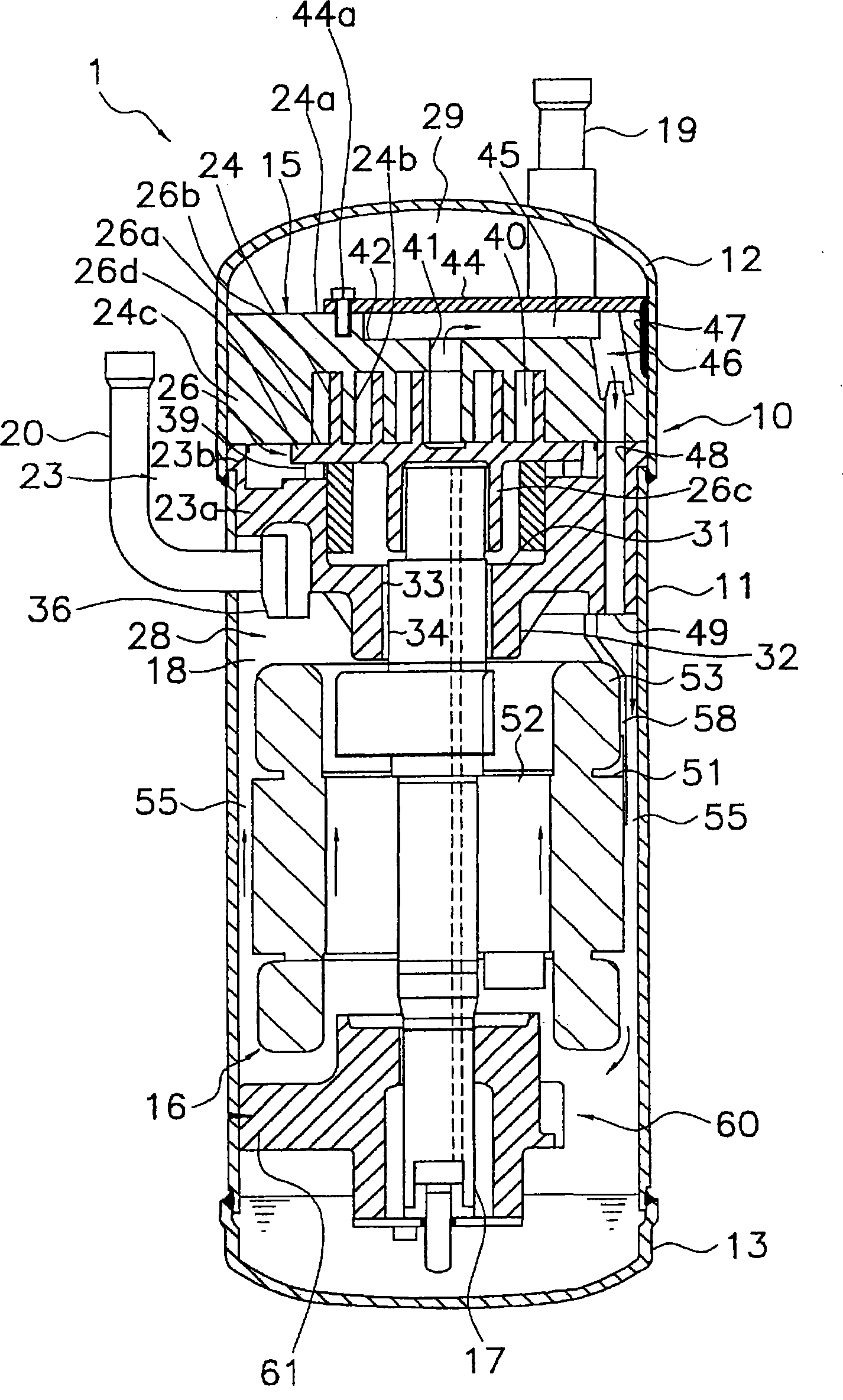
[0084] The high-low pressure dome scroll compressor 1 according to the first embodiment of the present invention constitutes a refrigerant circuit together with an evaporator, a condenser, an expansion mechanism, etc., and plays a role of compressing gas refrigerant in the refrigerant circuit, Such as figure 1 As shown, the high and low pressure dome-type scroll compressor 1 is mainly composed of a vertically long cylindrical sealed dome-shaped casing 10, a scroll compression mechanism 15, an Oldham ring (Oldham ring) 39, a driving motor 16, and a lower main bearing 60 , Suction pipe 19 and discharge pipe 20 constitute. The components of the high and low pressure dome scroll compressor 1 will be described in detail below.

[0085]

[0086] (1) Shell

[0087] The housing 10 has: a substantially cylindrical main body housing 11; a bowl-shaped upper wall 12 welded to the upper end of the main body housing 11 in an airtight manner; Bowl-shaped bottom wall portion 13 . In add...

no. 2 Embodiment approach

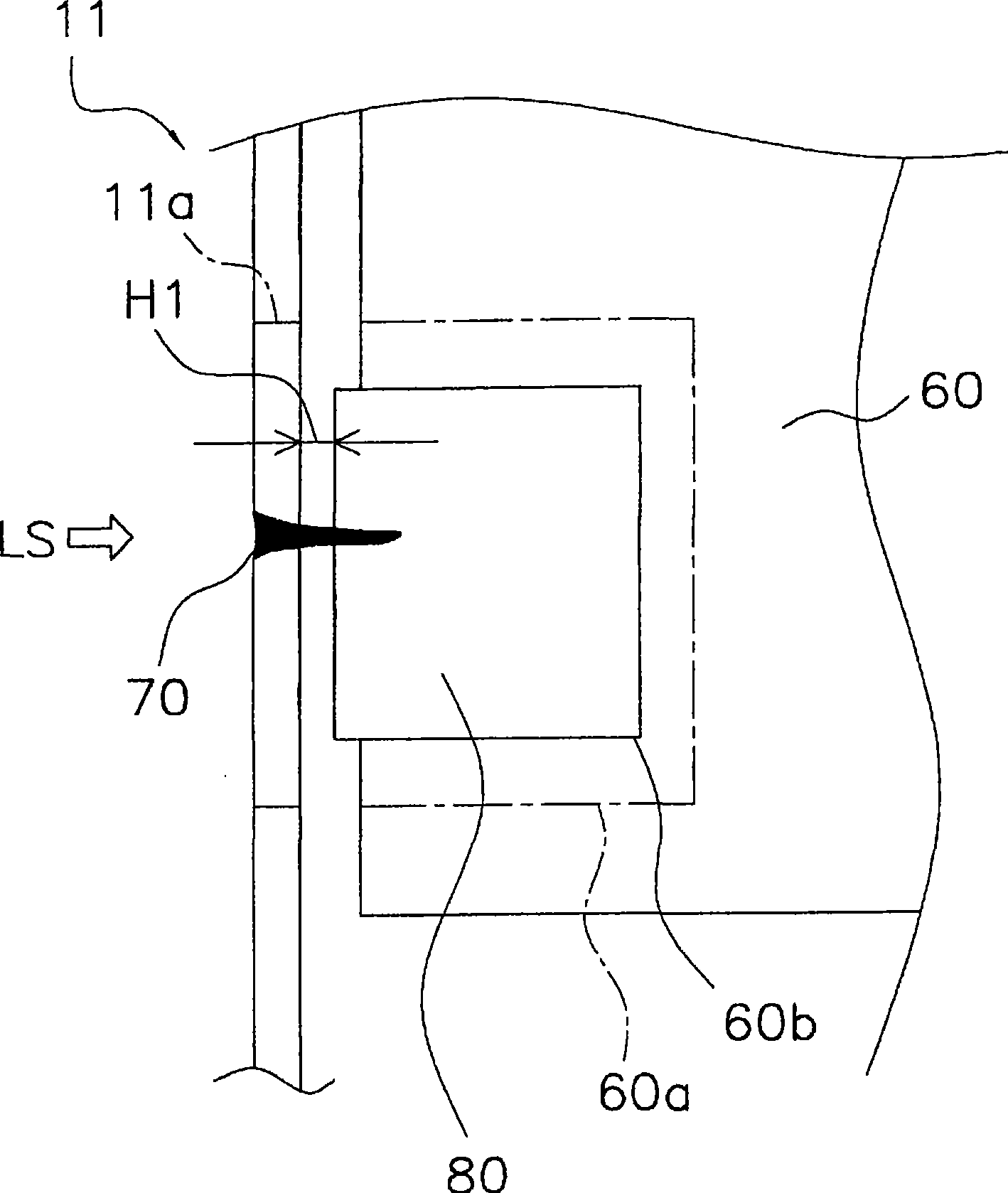
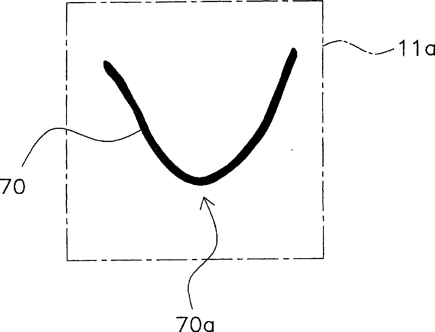
[0161] The high and low pressure dome type scroll compressor according to the second embodiment of the present invention has the same structure as the high and low pressure dome type scroll compressor 1 according to the first embodiment, however, the welding method of the main body casing and the lower main bearing Wait for the difference. Therefore, the welding method of the main body shell and the lower main bearing will be mainly explained here.

[0162] In addition, the high-low pressure dome scroll compressor of the second embodiment uses CO 2 (Carbon dioxide) is designed on the premise that the gas refrigerant to be compressed requires high pressure resistance. Therefore, the plate thickness of the main body shell 11, the upper wall shell 12, and the bottom wall shell 13 is 8 to 10 mm, which is different from the usual Compressors for refrigerants such as R410A are considerably thicker than the case thickness (3 to 4 mm).

[0163]

[0164] (1) Materials

[0165] The...

no. 3 Embodiment approach

[0183]

[0184]A rotary (more specifically, a swing) compressor 101 according to a third embodiment of the present invention is as follows: Figure 7 As shown, it mainly consists of an airtight dome-shaped housing 110, a swing compression mechanism 115, a driving motor 116, suction pipes 119a, 119b and a discharge pipe 119c. In this swing compressor 101 , an accumulator (gas-liquid separator) 190 is attached to the casing 110 .

[0185] In addition, compressor 101 to use CO 2 (Carbon dioxide) is designed on the premise that it is a gas refrigerant to be compressed.

[0186] (1) Shell

[0187] The housing 110 has: a substantially cylindrical main body housing part 111; a bowl-shaped upper wall housing part 112 welded to the upper end of the main body housing part 111 in an airtight manner; The bowl-shaped bottom wall housing part 113 of the first part. Further, the housing 110 mainly accommodates: a swing compression mechanism 115 for compressing gas refrigerant; and a dr...


PUM

PropertyMeasurementUnit
Thicknessaaaaaaaaaa
Plate thicknessaaaaaaaaaa
Thicknessaaaaaaaaaa

Abstract

A compressor where welding between a casing and an inner component or welding between a barrel casing and an end casing has sufficient strength and the welding has low strain achieved by suppressing an influence of heat by welding. A method of producing the compressor (1, 101) has a positioning process and a welding process. The compressor has the casing (10, 11, 111) and the inner component (60, 125) received in the casing. The casing has at its inner surface (11s, 111s) a first section (11a, 11w, 111w), and the inner component has a second section (60a, 61, 125b). The second section faces the first section. The first section and the second section are made to face each other in the positioning process. In the laser welding process, a laser beam is applied to at least a portion of the part where the first section and the second section are faced each other to laser-weld the casing and the inner component together.

Description

technical field [0001] The present invention relates to a manufacturing method of a compressor, in particular to a compressor in which a shell and internal parts are welded, and a compressor in which a main body shell and an end shell are welded. Background technique [0002] Conventionally, compressors such as scroll compressors and rotary compressors have been widely used in refrigeration devices and the like to compress refrigerants. [0003] In these compressors, internal components arranged inside the casing are fixed to the main body casing by spot welding. For example, in the compressor of Patent Document 1, the bearings that pivotally support the rotating shaft of the electric motor and the main body casing are joined by spot welding at multiple positions from the outside of the main body casing. Specifically, the bearing is fixed to the main body casing by opening a hole in the main body casing and performing arc welding (TIG welding, etc.) using a filler material ...

Claims


Application Information

Patent Timeline
IPC IPC(8): F04C29/00B23K26/02B23K26/20F04B39/12B23K26/21
Inventor 岸川光彦广内隆梶原干央山路洋行山本哲新井美绘
Owner DAIKIN IND LTD
Why Eureka
Try Eureka