

Hydraulic drive system with energy recuperation
Patent Information
- Authority / Receiving Office
- CN · China
- Patent Type
- Applications(China)
- Current Assignee / Owner
- LIEBHERR WERK NENZING
- Publication Date
- 2009-04-01
Smart Images
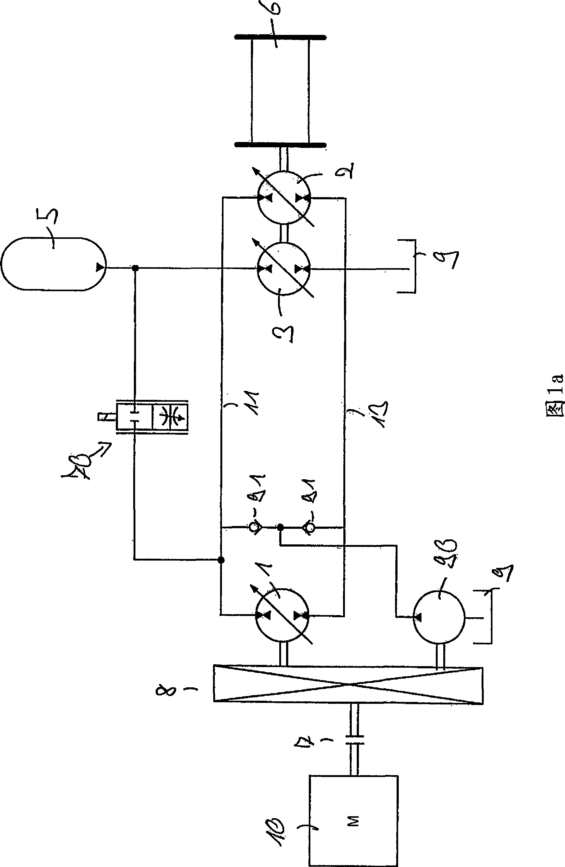
Figure 1 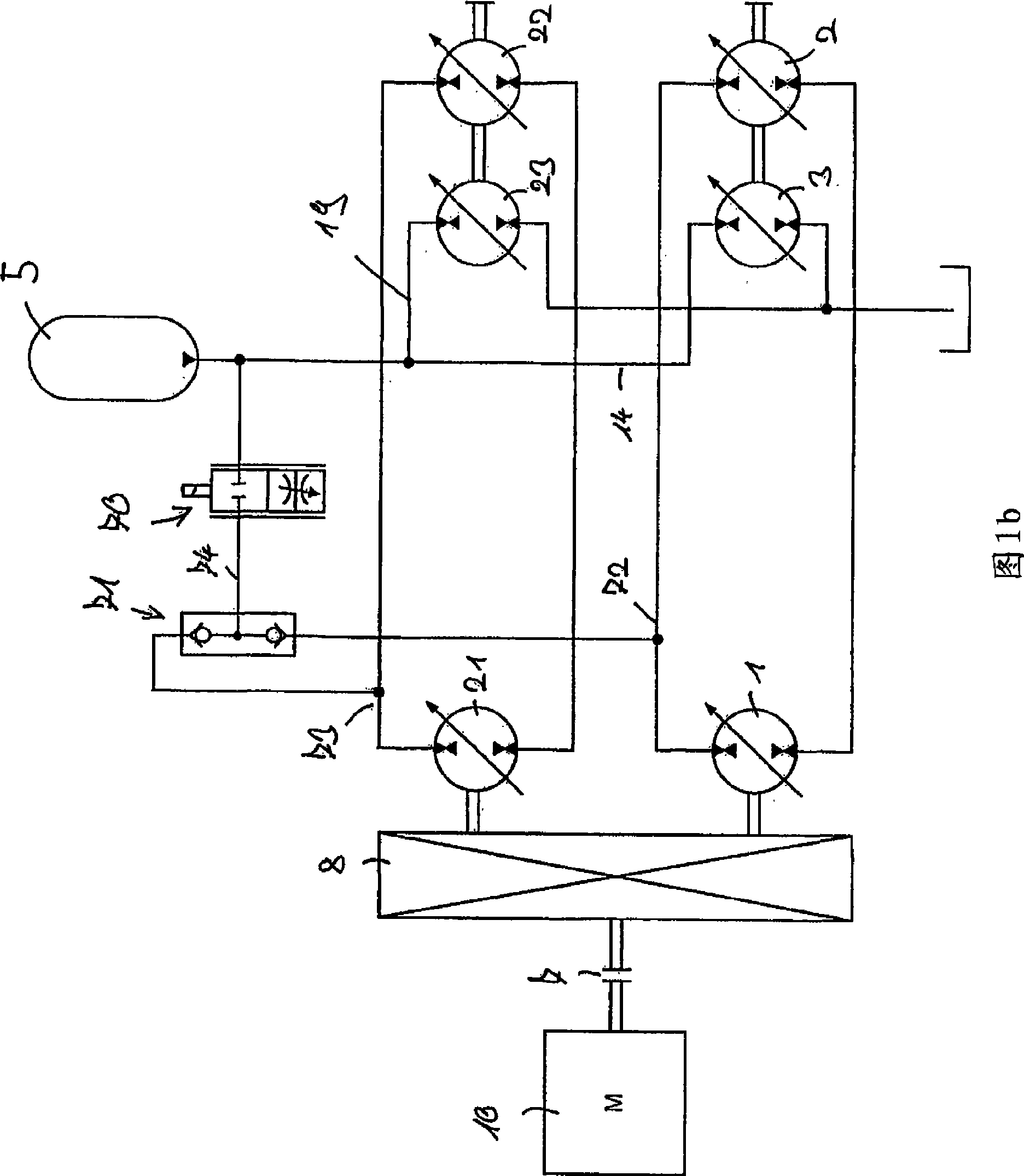
Figure 2 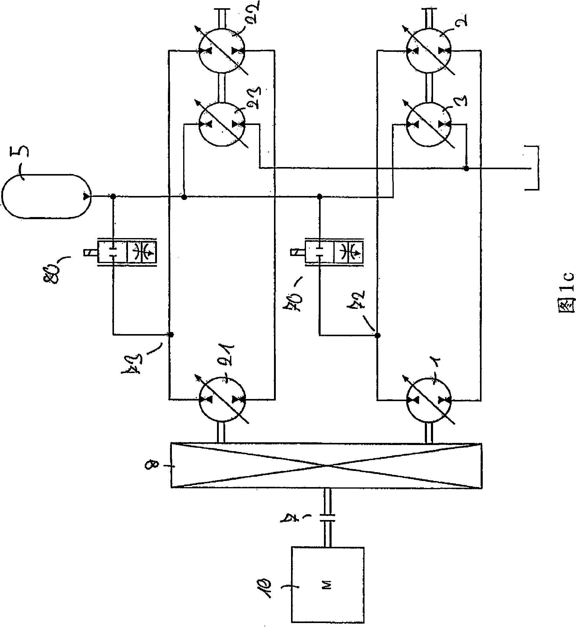
Figure 3
Abstract
Description
technical field
[0001] The present invention relates to a hydraulic drive system for driving equipment, the hydraulic drive system having a drive unit capable of driving said hydraulic machine via a main hydraulic circuit comprising a first positive displacement hydraulic machine and a second positive displacement hydraulic machine equipment; a third positive displacement hydraulic machine connectable or connectable to said device to transfer mechanical energy; and a high pressure accumulator hydraulically connected or connectable to the third positive displacement hydraulic machine hydraulic machine. In particular, the present invention relates to a hydraulic drive system for use in cranes, especially for driving winches. In addition, the invention relates to a hydraulic drive system for use in mobile equipment, in particular in reach cranes or wheel loaders, in particular as a travel drive. Background technique
[0002] In order to provide the hydraulic energy used to dr...