Iron member detecting method and device of constant magnetic deironing device by sound wave

An acoustic wave detection device and acoustic wave detection technology are applied in chemical instruments and methods, analysis of solids using sonic/ultrasonic/infrasonic waves, magnetic separation, etc. Simple, extended service life, low mechanical loss

Active Publication Date: 2009-04-01
BAOSHAN IRON & STEEL CO LTD +1
View PDF1 Cites 6 Cited by
  • Summary
  • Abstract
  • Description
  • Claims
  • Application Information

AI Technical Summary

Problems solved by technology

[0007] In the above-mentioned first type of prior art, as long as the material transport belt is running, regardless of whether there are iron parts in the material, the iron removal belt of the belt-type constant magnetic iron remover must always keep running. This constant magnetic iron removal technology is currently used because of its simple control. More common, but its disadvantages are large power consumption and large mechanical loss
The second type of existing technology is limited by the sensitivity of the metal detection device, and some small iron parts cannot be detected, which will easily cause a large number of iron parts to accumulate and cause the iron removal belt to be too loaded and cannot be removed by rotation
Although the iron remover has many obvious advantages, the method of mounting the pressure detection device on the surface of the permanent magnet has the disadvantages of complicated structure, inconvenient adjustment and high cost.

Method used


Image

  • Iron member detecting method and device of constant magnetic deironing device by sound wave
  • Iron member detecting method and device of constant magnetic deironing device by sound wave
  • Iron member detecting method and device of constant magnetic deironing device by sound wave

Examples


Embodiment Construction

[0026] The present invention will be further described below in conjunction with the accompanying drawings and specific embodiments.

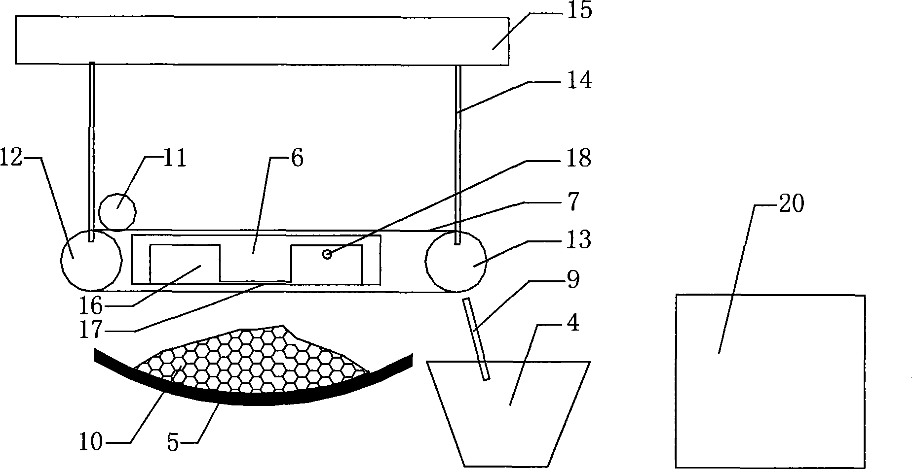
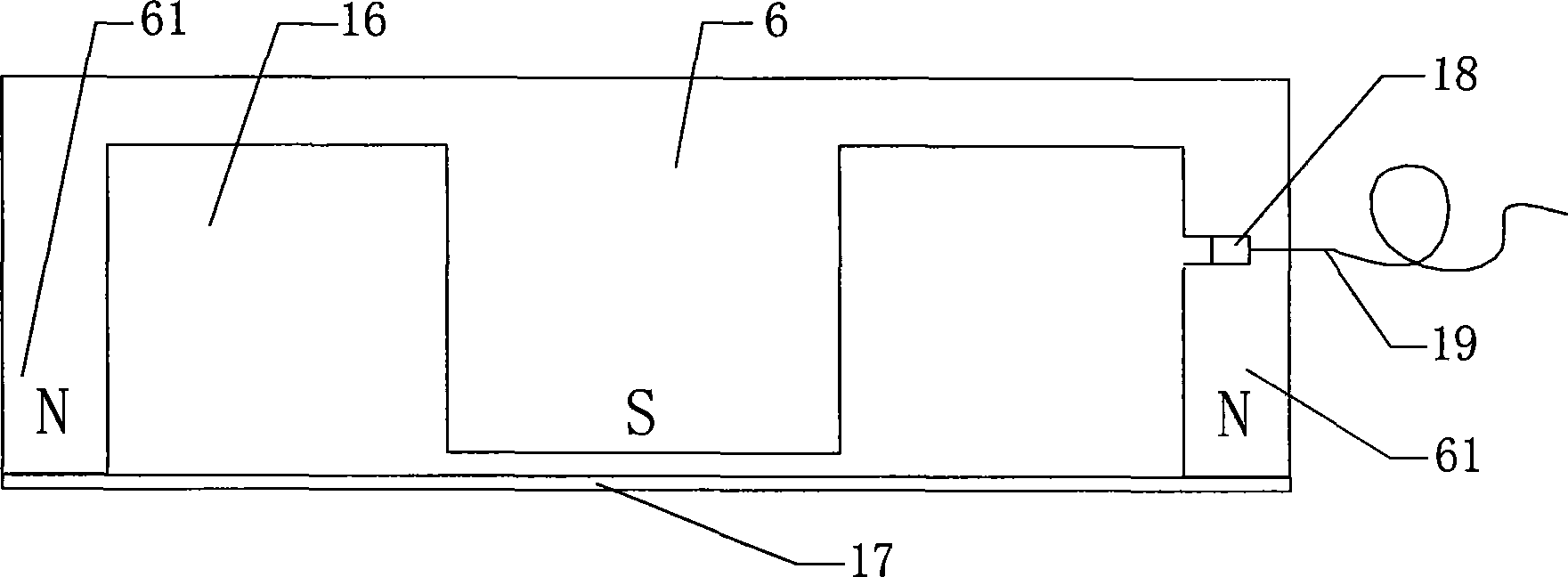
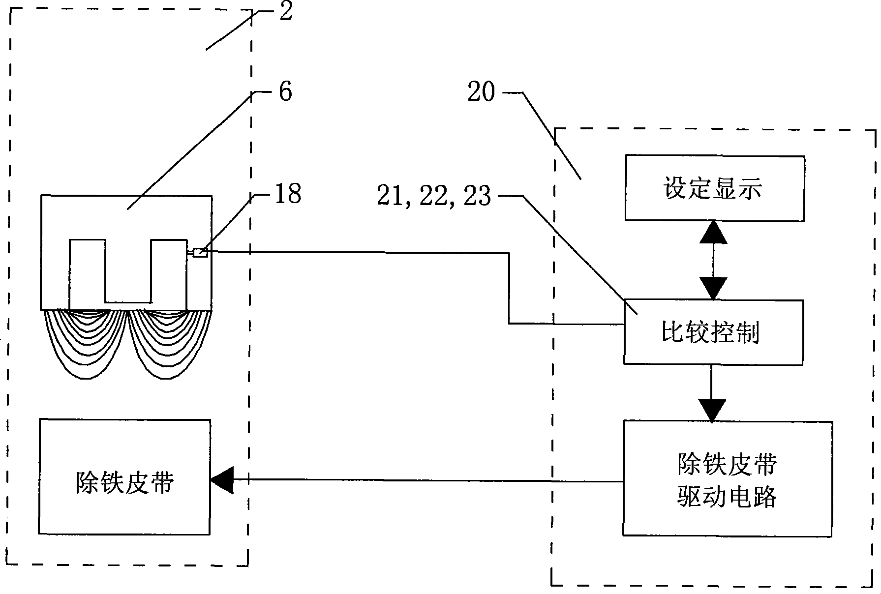
[0027] see figure 1 , figure 2 , image 3 , Figure 4 , a constant magnetic iron remover adopts a device for detecting iron parts by sound waves, mainly consisting of an iron remover control box (controller) 20, a belt type constant magnetic iron remover 2 with sound wave detection, and a discarded iron hopper 4. Three parts Equipment composition. The belt-type constant magnetic iron remover 2 with acoustic wave detection includes a constant magnet 6, a non-magnetic separator 17, an acoustic wave detection device 18, a circular iron removal belt 7, an iron removal belt drive motor 11, an iron removal belt drive roller 12, an iron removal belt Iron belt support roller 13.

[0028] Constant magnet 6 is made up of middle magnet and surrounding constant magnet yoke 61, and constant magnet yoke 61 is a magnetizer, as iron plate, forms constan...


PUM


Abstract

The invention relates to a permanent magnet iron remover used for automatically removing inclusion steel and iron parts in materials from a dispersed solid non-magnetic material conveyer belt. A method that the permanent magnet iron remover adopts acoustic wave to detect the iron parts comprises the following steps: the lower part of the permanent magnet yoke is provided with a non-magnetoconductivity baffle, the permanent magnet yoke and the non-magnetoconductivity baffle circles a space which forms a sealed chamber, an acoustic wave detecting device is arranged in a hole which is opened at one side of the permanent magnet yoke and is communicated with the sealed chamber, the sound wave detecting device converts an acoustic signal and outputs an electrical signal to a control box of the iron remover; the electrical signal is calculated by a comparison control circuit in the control box and then output to be connected with an operating power supply of an iron-removing belt, thus controlling the rotation of the iron-removing belt. The invention can automatically detect that whether iron parts are absorbed by the permanent magnet and has simple structure, convenient use and debugging and high efficiency; the iron-removing belt does not need continuous running for a long time, and runs only when the iron parts are absorbed; besides, the invention can save electrical energy, has little consumption and can prolong the service life of the iron remover.

Description

technical field [0001] The present invention relates to a constant magnetic iron remover for automatically removing iron and steel parts from bulk solid non-magnetic material conveyor belts, in particular to a method and device for the constant magnetic iron remover to detect iron parts using sound waves to protect belt conveyors and subsequent processes The equipment is protected from damage and can be used in metallurgy, coal, power generation, cement, papermaking, ports and other industries. Background technique [0002] At present, belt-type constant magnetic iron remover is widely used at home and abroad to automatically remove iron inclusions in non-magnetic materials. The advantage of belt-type constant magnetic iron remover is that it does not need to be energized to consume electric energy like the electromagnetic iron remover used in the early stage. The belt type constant magnetic iron remover is equipped with a belt type constant magnetic iron remover, a control ...

Claims


Application Information

Patent Timeline
Patent Type & Authority Applications(China)
IPC IPC(8): G01N29/04B03C1/00
Inventor 韩明明江通吴剑民
Owner BAOSHAN IRON & STEEL CO LTD
Why Eureka
Try Eureka