
Heat treatment method and heat treatment apparatus

A heat treatment method and technology of a heat treatment device are applied in the field of ensuring uniformity of processing, which can solve the problem of difficulty in increasing the number of mounted blocks, and achieve the effects of enhancing uniformity of processing, increasing spacing and ensuring the number of mounted blocks

Active Publication Date: 2011-05-18
TOKYO ELECTRON LTD
View PDF3 Cites 0 Cited by
  • Summary
  • Abstract
  • Description
  • Claims
  • Application Information

AI Technical Summary

Problems solved by technology

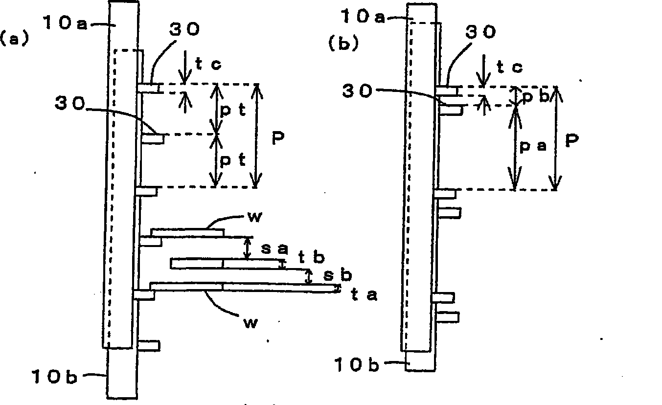
[0007] However, in the above-mentioned heat treatment apparatus, the pitch width of the number of wafers loaded on the wafer boat is set to a minimum value from the viewpoint of uniformity in the processing plane and between planes and the viewpoint of transfer, and it is difficult to increase the number of wafers to be loaded.

Method used


Image

  • Heat treatment method and heat treatment apparatus
  • Heat treatment method and heat treatment apparatus
  • Heat treatment method and heat treatment apparatus

Examples


no. 1 approach

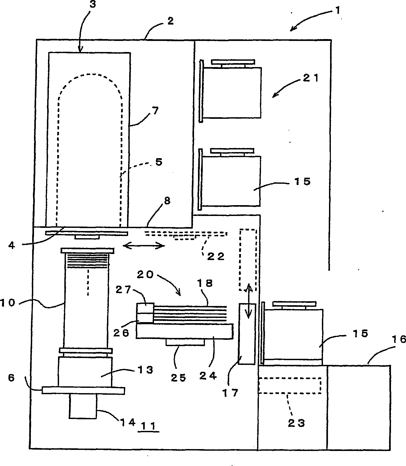
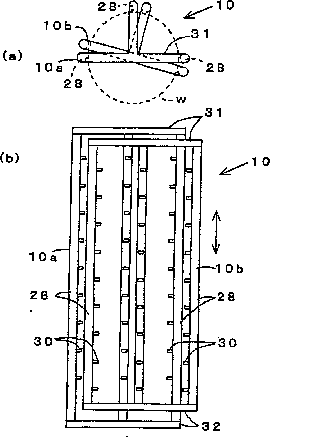
[0064] Below, the best mode for carrying out the present invention will be described in detail with reference to the drawings. figure 1 A longitudinal sectional view schematically showing a heat treatment apparatus according to an embodiment of the present invention, figure 2 It is a figure which schematically shows an example of a board|substrate holder, (a) is a top view, (b) is a front view.

[0065] exist figure 1 Among them, 1 is a vertical heat treatment device, and the heat treatment device 1 has a frame body 2 forming an outer shell. A vertical heat treatment furnace 3 is arranged above the frame body 2, wherein the heat treatment furnace 3 is used to accommodate a plurality of substrates to be processed, such as thin disc-shaped semiconductor wafers w, and to perform predetermined treatments, such as CVD treatment, on them. Wait. This heat treatment furnace 3 mainly comprises: the vertically long treatment container of lower part as furnace mouth 4 openings, such ...

no. 2 approach

[0094] Hereinafter, the best mode for carrying out the present invention will be described in detail with reference to the drawings. Figure 13 It is a longitudinal sectional view schematically showing a heat treatment apparatus according to an embodiment of the present invention, Figure 14 This is an explanatory diagram schematically illustrating an example in which two wafers are supported with their back faces facing each other using a support ring, Figure 15 It is a front view schematically showing the state in which two wafers are held on the wafer boat in the vertical direction and at a predetermined interval using the support ring, Figure 16 is a diagram representing a support ring, Figure 16 (a) is an overall schematic perspective view, Figure 16 (b) is an enlarged perspective view of main parts.

[0095] exist Figure 13 Among them, 101 is a vertical heat treatment device, and the heat treatment device 101 has a frame body 102 forming an outer shell. A verti...


PUM


Abstract

A heating processing method and a heat processing device capable guaranteeing the evenness and increasing the carrying block number of a substrate keeping component compared with the current are provided. The substrate holder (10) holds a plurality of substrates (w) at predetermined vertical intervals. The substrate holder (10) is carried into a heat treating furnace (3). A predetermined heat treatment is performed on the substrates. The substrate holder (10) has two holder constituting bodies (10a, 10b). Each of the holder (10a, 10b) constituting bodies has a plurality of columns (28) and substrate holding sections (30). The columns (28) are arranged on the circumference of the same imaginary circle. The substrate holding sections (30) hold circumferential portions of the respective substrates (w) and are mounted on each column (28). One of the holder constituting bodies (10) holds the substrates under the condition that front surfaces of the substrates face upward, while the other of the holder constituting bodies (10b) holds the substrates under the condition that back surfaces of the substrates face upward. The substrate (w) with the front surface facing upward and the substrate with the back surface facing upward are alternately arranged in a vertical direction.

Description

[0001] References to related applications [0002] This patent application enjoys the benefit of Japanese application "Japanese Patent Application No. 2007-249039" and "Japanese Patent Application No. 2007-249040" filed on September 26, 2007, and the entire disclosure content of these earlier applications is incorporated as a part of this specification. technical field [0003] The invention relates to a heat treatment method and a heat treatment device, in particular to a technique for ensuring treatment uniformity and increasing the number of treatment blocks. Background technique [0004] In the manufacture of semiconductor devices, various processing devices (semiconductor manufacturing devices) are used to perform oxidation, diffusion, CVD (Chemical Vapor Deposition) and other treatments on substrates to be processed, such as semiconductor wafers (lower surface, also called wafers). Furthermore, as one of the processing apparatuses, a vertical heat processing apparatus ...

Claims


Application Information

Patent Timeline
Patent Type & Authority Patents(China)
IPC IPC(8): H01L21/00H01L21/673F27D5/00
Inventor 井上久司松本俊一竹内靖
Owner TOKYO ELECTRON LTD
Learn More