

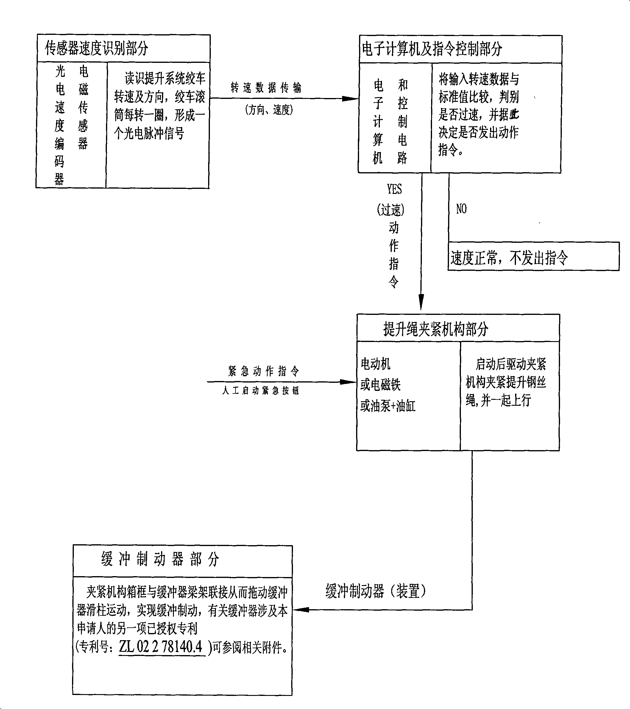
Rope type flexible hoisting overspeed overtravel protection buffering braking system
A kind of buffer braking and flexible technology, applied in the direction of hoisting device, mainspring mechanism, etc., can solve the problems of protection failure, rapid decrease of friction coefficient, temperature rise, etc. , Improve the effect of buffering effect
- Summary
- Abstract
- Description
- Claims
- Application Information
AI Technical Summary
Problems solved by technology
Method used
Image

Examples
Embodiment Construction
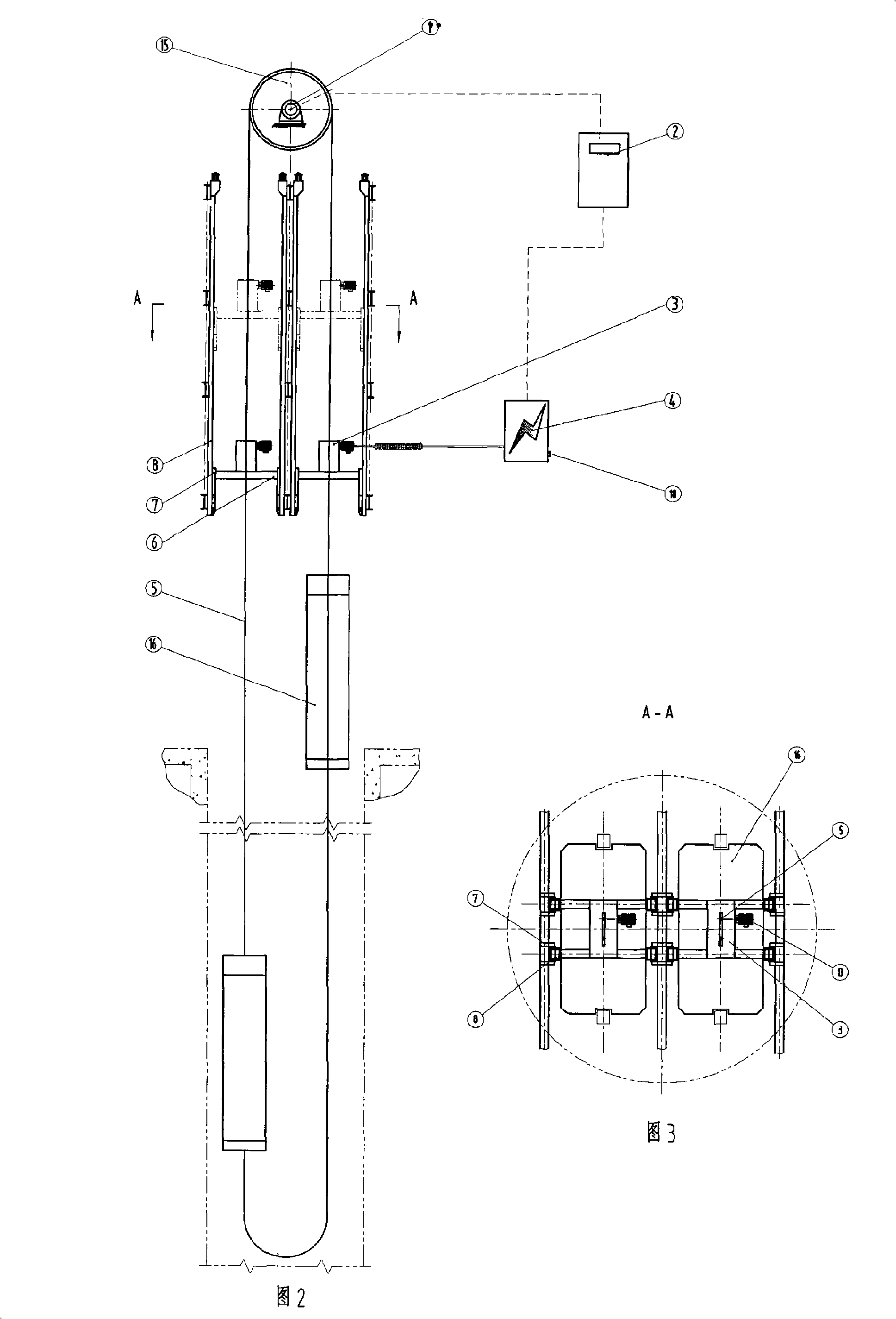
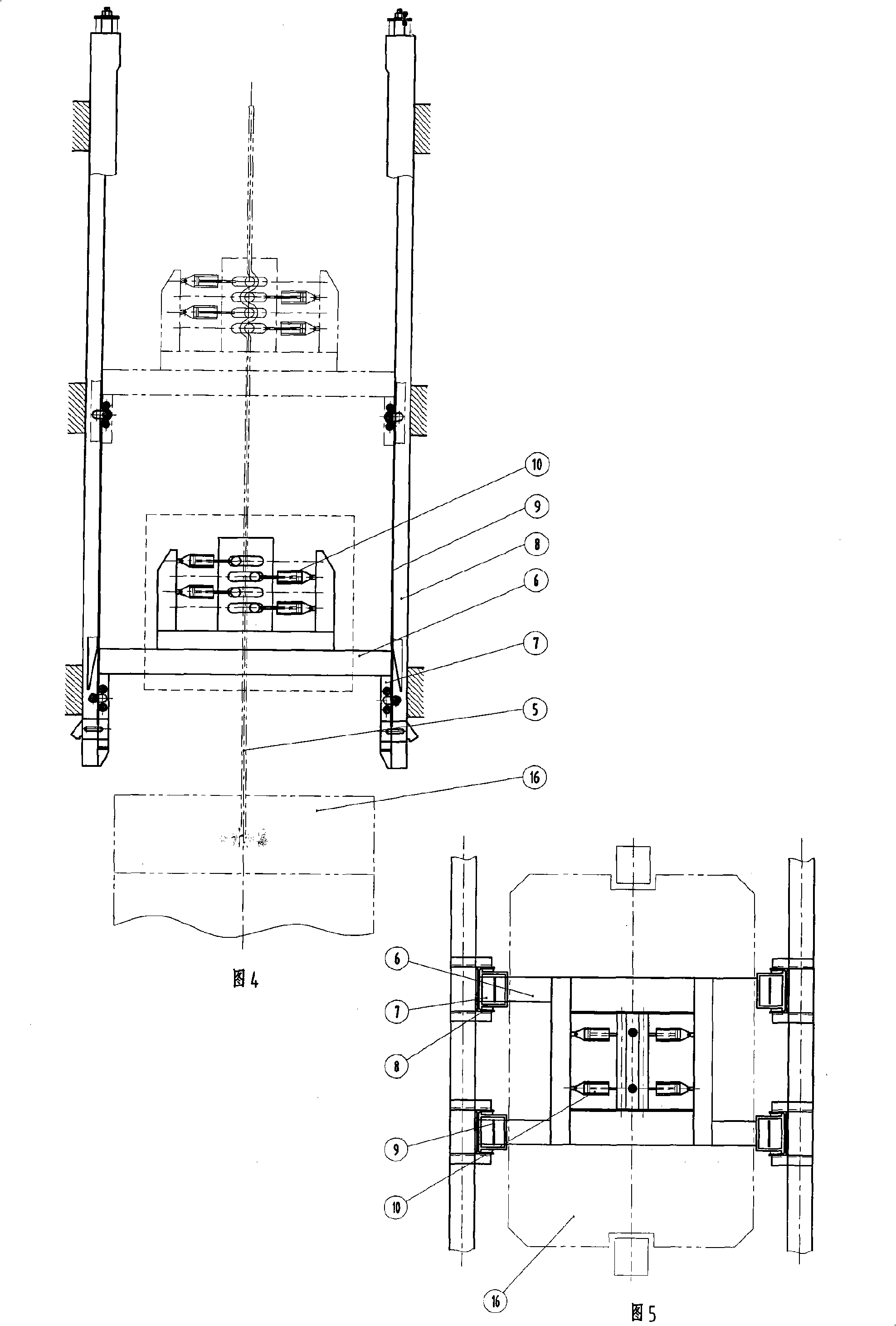
[0032] The structure disclosed in the above drawings is the structure of the embodiment of the present invention. In the figure, the parts represented by each label are:
[0033] 1- Photoelectric encoder or sensor;
[0034] 2- Computer control cabinet;
[0035] 3- lifting rope clamping mechanism;
[0036] 4- The power control cabinet of the clamping mechanism;
[0037] 5- Hoisting wire rope;
[0038] 6- The beam of the buffer brake device;
[0039] 7- The strut of the buffer brake device;
[0040] 8- The sleeve of the buffer brake device;
[0041] 9- The steel belt on the column;
[0042] 10- The pressure roller group of the clamping mechanism;
[0043] 11- box frame;
[0044] 12- eccentric disc;
[0045] 13- electric motor;
[0046] 14- gear payment;
[0047] 15- hoist (winch);
[0048] 16- lifting container;
[0049] 17- Inclined rail of the inclined roller clamping mechanism (thickness is about tens of millimeters);
[0050] 18- Manual emergency stop button. ...
PUM
 Abstract
Description
Claims
Application Information