
Air-float pool for treating wastewater from melting

A technology for wastewater treatment and air flotation tank, which is applied in flotation water/sewage treatment and other directions, and can solve the problems of poor oil removal effect, short residence time and insufficient height.

Inactive Publication Date: 2010-09-01
SHANXI TAIGANG ENG TECH +1
View PDF0 Cites 0 Cited by
  • Summary
  • Abstract
  • Description
  • Claims
  • Application Information

AI Technical Summary

Problems solved by technology

The height of the existing air flotation partition wall is not enough, and the residence time of the water flow in the contact chamber is short. In this way, many air bubbles with oily stains cannot float to the water surface, but remain in the effluent water and are taken away by the effluent water, and the effect of removing oil stains is poor; There is no gap between the wall and the bottom of the pool, and the sludge deposited in the contact area cannot be cleaned. After a long time, a large amount of sludge accumulates, and it cannot flow away with the water until it is higher than the top of the partition wall; due to the sludge accumulation, the releaser is blocked

Method used


Image

  • Air-float pool for treating wastewater from melting
  • Air-float pool for treating wastewater from melting
  • Air-float pool for treating wastewater from melting

Examples


Embodiment 1

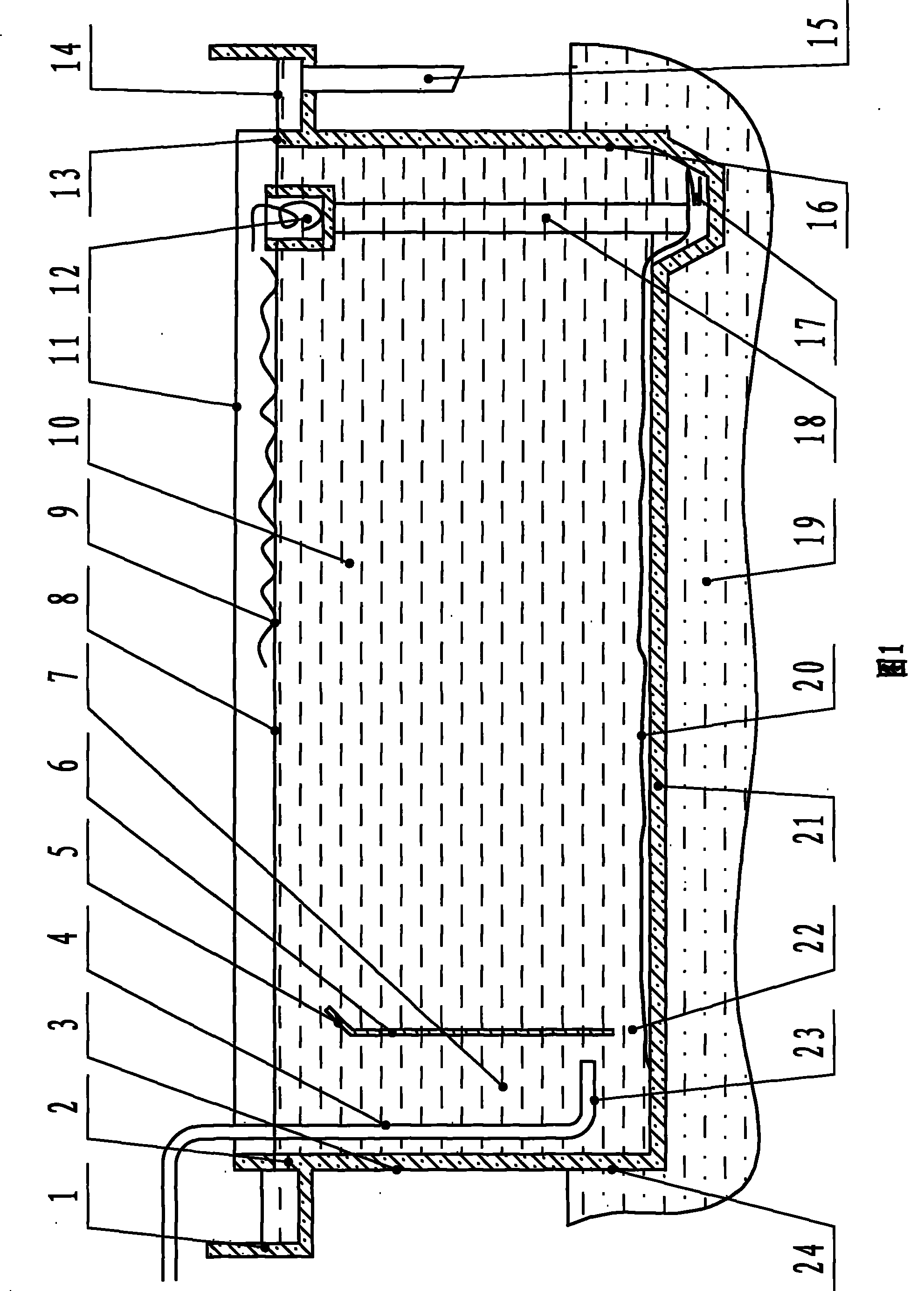
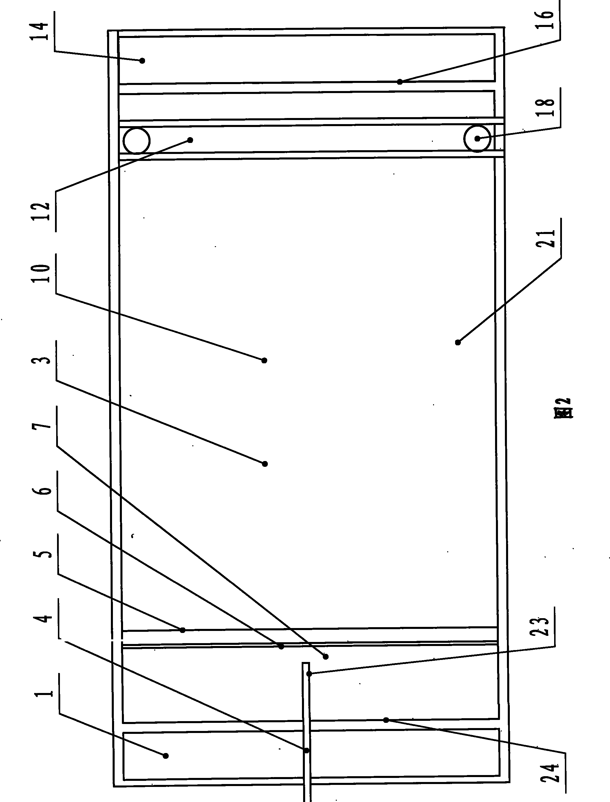
[0024] figure 1 and figure 2 The described air flotation tank for smelting wastewater treatment includes a pool body 3, a partition wall 6, an inlet channel 1, an outlet channel 14, a release device 23 and a slag discharge tank 12, and the partition wall 6 is horizontally arranged in the pool body 3 to separate the pool body 3 The inside is divided into a contact chamber 7 and a separation chamber 10. The water inlet channel 1 is arranged on the upper part of the front wall 24 of the water inlet side outside the pool body 3, and 50 water distribution holes 2 communicating with the water inlet channel 1 are distributed on the pool body 3. , the outlet channel 14 is arranged on the upper part of the rear wall 16 of the outlet side of the pool body 3 outside, and the outlet weir 13 communicating with the outlet channel 14 is arranged on the pool body 3, and the slag discharge groove 12 is arranged horizontally in the pool body 3 On the upper part of the water outlet side, a sl...

Embodiment 2

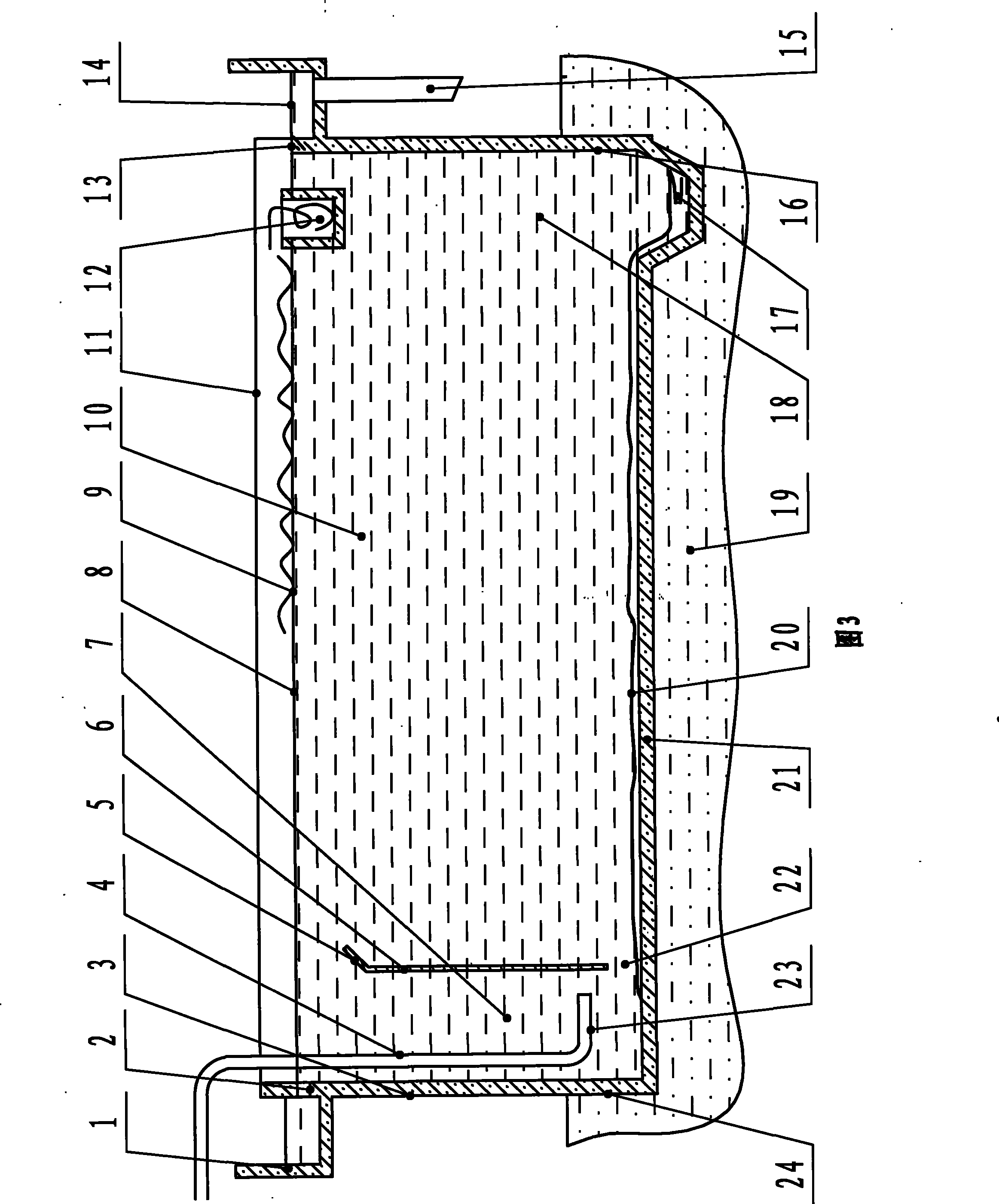
[0028] The structure of this embodiment see image 3 and Figure 4 , The difference between this embodiment and Embodiment 1 is that the two ends of the slag discharge tank 12 extend outside the pool body 3, and the slag discharge pipe 25 connected with the slag discharge pipe 12 is arranged outside the pool body 3.


PUM

PropertyMeasurementUnit
heightaaaaaaaaaa

Abstract

The invention relates to a floatation pool for processing waste water from smelting. The floatation pool comprises a pool body, a partition wall, a water inlet channel, a water outlet channel, a releaser and a slag runner, wherein the partition wall is arranged inside the pool body to separate the pool body into a contact chamber and a separation chamber, a mud collecting hopper is arranged on a water outlet square on the bottom in the pool body, the releaser is arranged in the contact chamber near the bottom of the pool, one end of the releaser is communicated with one end of a releasing branch pipe, and the other end of the releasing branch pipe is extended out of a pool port. The floatation pool is characterized in that the partition wall is 0.6m to 1.0m away from the water inlet inside of the pool body; the height of the partition wall self is 4.2m to 4.8m; and the partition wall is 80mm to 110mm away from the bottom of the pool body. A baffler which is inclined in the direction of water flow can be arranged on the top of the partition wall. The floatation pool for processing the waste water from smelting has the advantages of good oily stain removal effect and convenient sludge cleaning.

Description

technical field [0001] The invention relates to an air flotation pool for treating smelting wastewater. Background technique [0002] Air flotation is a technology commonly used in wastewater treatment to remove oil. The air flotation treatment method is to introduce or generate a large number of fine air bubbles in the water to make them attach to the suspended oil particles, increase the buoyancy of the suspended particles, and use the principle of buoyancy to make the oil float on the water surface, thereby achieving the purpose of degreasing. [0003] The air flotation tank is divided into a contact chamber and a separation chamber by a partition wall to complete the full contact, adhesion and floating of the microbubbles and impurities in the water. The height of the existing air flotation partition wall is not enough, and the residence time of the water flow in the contact chamber is short. In this way, many air bubbles with oily stains cannot float to the water surfa...

Claims


Application Information

Patent Timeline
Patent Type & Authority Patents(China)
IPC IPC(8): C02F1/24
Inventor 赵瑞峰武彦琴高俊飞
Owner SHANXI TAIGANG ENG TECH
Learn More