Continuous vacuum transition chamber with linear vacuum motive seal and X-ray radiation protection function

A protection function and dynamic sealing technology, applied in the field of continuous vacuum transition chamber, can solve the problems of low work efficiency, difficult X-ray protection, large leakage, etc., and achieve the effect of high work efficiency

Active Publication Date: 2011-05-11
宿迁三鑫科技有限公司
View PDF0 Cites 0 Cited by
  • Summary
  • Abstract
  • Description
  • Claims
  • Application Information

AI Technical Summary

Problems solved by technology

This kind of device needs to amplify the air to take out the workpieces after processing one or a batch of workpieces each time, then put in new workpieces and then vacuumize to reach the working vacuum required for electron beam processing before processing, and the work efficiency is low.
[0003] Some electron beam continuous processing devices / production lines, such as the continuous electron beam steel strip vacuum coating production line, adopt the pressure roller type continuous dynamic sealing method. Since the installation of the pressure roller needs to reserve a supporting position, the gap left is large, and the vacuum dynamic The sealing effect is not good, the load of the vacuum pump is very large, a high-power vacuum pump is required to maintain the required working vacuum, and the vacuum pump is easily damaged
[0004] For continuously operating electron beam processing vacuum equipment, especially for high-voltage electron beam processing equipment above 60KV, X-ray protection will become more difficult because the continuous operation of the inlet and outlet must be reserved

Method used


Image

  • Continuous vacuum transition chamber with linear vacuum motive seal and X-ray radiation protection function
  • Continuous vacuum transition chamber with linear vacuum motive seal and X-ray radiation protection function

Examples


Embodiment Construction

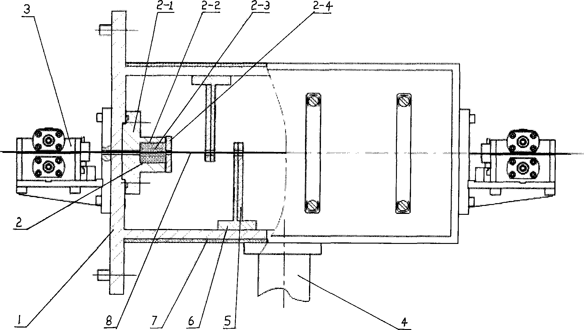
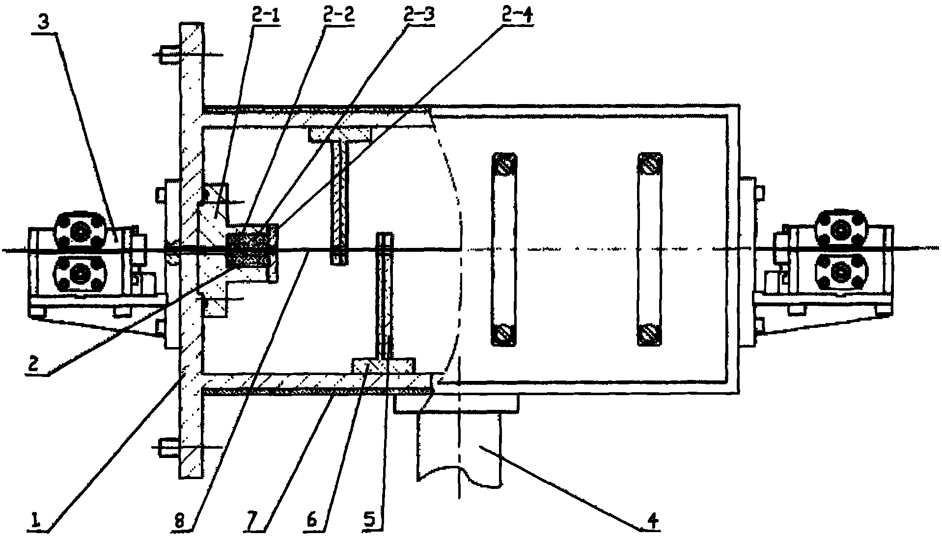
[0012] The continuous vacuum transition chamber of the present invention consists of a transition chamber box body 1, a linear dynamic sealing device 2 in the transition chamber, an adjustable flange sealing frame 2-1, a cover plate 2-2, an upper and lower sealing pressure plate 2-3, and an upper and lower sealing pressure block 2 -4. The guide device at both ends of the box body 3, the vacuum exhaust pipe 4, the lead baffle 5, the lead baffle bracket 6, and the protective lead 7 outside the transition box. The upper and lower sealing pressure plates 2-3 are made of materials with a small friction coefficient The inner side of the upper and lower sealing pressure plates 2-3 matches the shape of the strip metal 8, the upper and lower sealing pressure plates 2-3 are upper and lower sealing pressure blocks 2-4 made of elastic materials, and the sealing channel is set at more than 2 levels to form a linear The dynamic sealing device 2, X-ray lead baffles 5 with lead plates staggere...


PUM


Abstract

The invention discloses a continuous vacuum transition chamber with linear vacuum dynamic sealing and X ray protection functions, which is characterized in that: the continuous vacuum transition chamber consists of a transition chamber box body, more than two linear dynamic sealing devices arranged in the transition chamber box body, a guiding device at the two ends of the box body, a pipeline ofthe vacuum pumping pipe, lead baffles, a bracket for the lead baffles and protective lead arranged outside the transition chamber box body; an upper sealing block and a lower sealing block of the linear dynamic sealing device tightly press the sealing pressure plate, thus forming a vacuum-tight linear dynamic sealing channel; X ray protection lead baffles which are provided with lead plates and staggered up and down are arranged between the dynamic sealing devices, the vacuum transition chamber is coated with protection lead, and the vacuum pumping pipe is connected with a vacuum pump. The continuous vacuum transition chamber has the advantages as follows: the vacuum degree / pressure of the vacuum working chamber can be ensured to reach 0.5 to 1Pa under the running state of the continuous passing through of ribbon metal materials; X ray dose reaches safe dose at the inlet and outlet, the load of the vacuum pump is relatively small, the vacuum device can run continuously and stably for a long time and the work efficiency of processing equipment is high.

Description

technical field [0001] The invention relates to a continuous vacuum transition chamber, in particular to a continuous vacuum transition chamber with linear vacuum dynamic sealing and X-ray protection functions. Background technique [0002] Most of the electron beam processing devices seal the workpiece in an independent airtight vacuum chamber. This kind of device needs to amplify the air to take out the workpieces after processing one or a batch of workpieces each time, then put in new workpieces and then vacuumize to reach the working vacuum required for electron beam processing before processing, and the work efficiency is low. . [0003] Some electron beam continuous processing devices / production lines, such as the continuous electron beam steel strip vacuum coating production line, adopt the pressure roller type continuous dynamic sealing method. Since the installation of the pressure roller needs to reserve a supporting position, the gap left is large, and the vacuum...

Claims


Application Information

Patent Timeline
Patent Type & Authority Patents(China)
IPC IPC(8): C23C14/56
Inventor 宋宜梅黄以平李少林
Owner 宿迁三鑫科技有限公司
Why Eureka
Try Eureka