Double-wall sleeve suspension type high-pressure gas underground storing well installation method and structure thereof

A high-pressure gas and suspension technology, which is applied in mining equipment, earthwork drilling, storage equipment, etc., can solve the problems of poor sealing effect of natural gas and impossible removal of cement, and achieve the effect of avoiding self-pressurization and corrosion

Active Publication Date: 2009-04-08
TIANJIN SPECIAL EQUIP INSPECTION INST
View PDF0 Cites 17 Cited by
  • Summary
  • Abstract
  • Description
  • Claims
  • Application Information

AI Technical Summary

Problems solved by technology

[0011] Since the cement slurry reaches the lower part through the inner wall of the well, the cement slurry returns from the annular space around the outer wall of the well, and the bottom structure of the well is

Method used


Image

  • Double-wall sleeve suspension type high-pressure gas underground storing well installation method and structure thereof
  • Double-wall sleeve suspension type high-pressure gas underground storing well installation method and structure thereof
  • Double-wall sleeve suspension type high-pressure gas underground storing well installation method and structure thereof

Examples


Embodiment 1

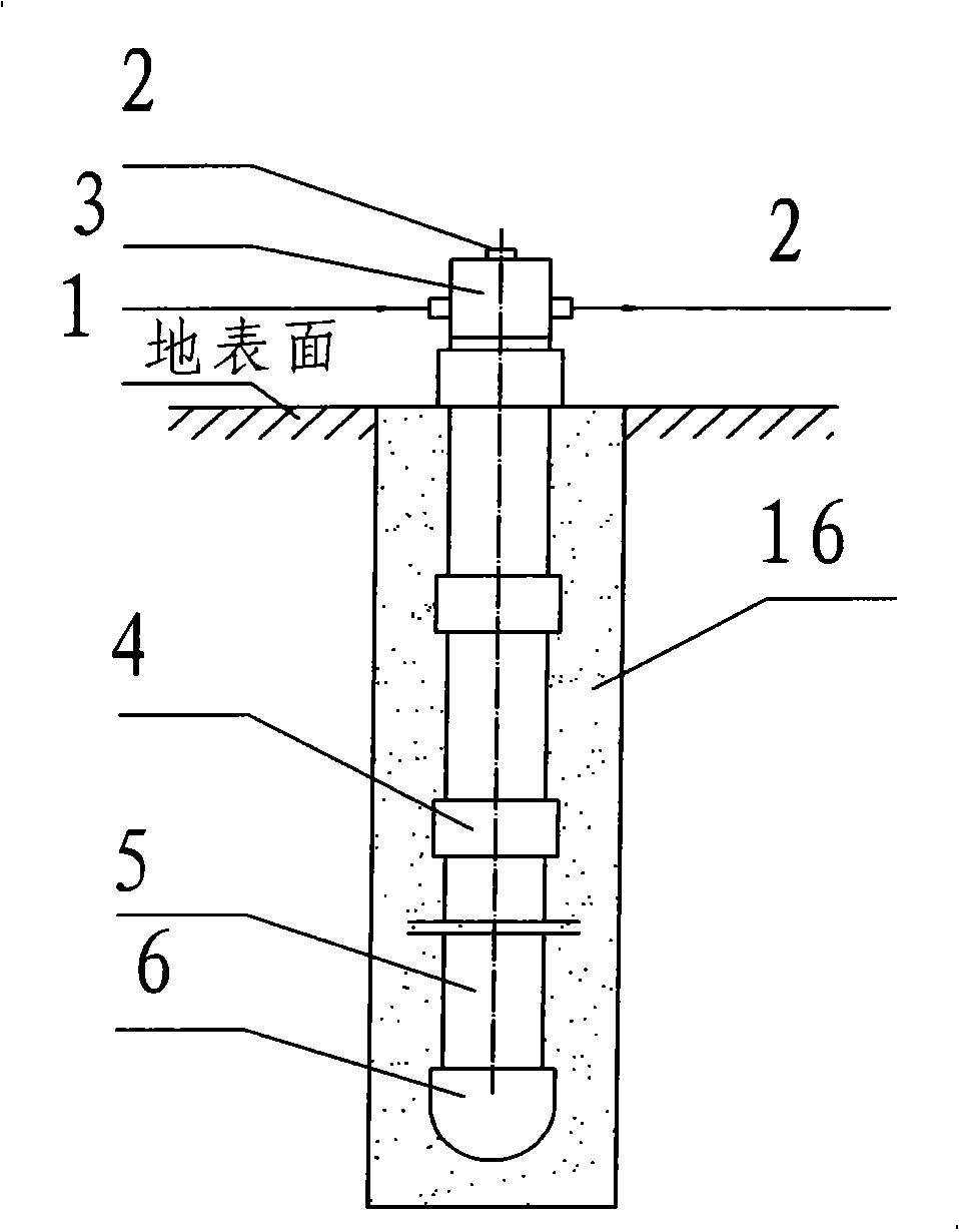
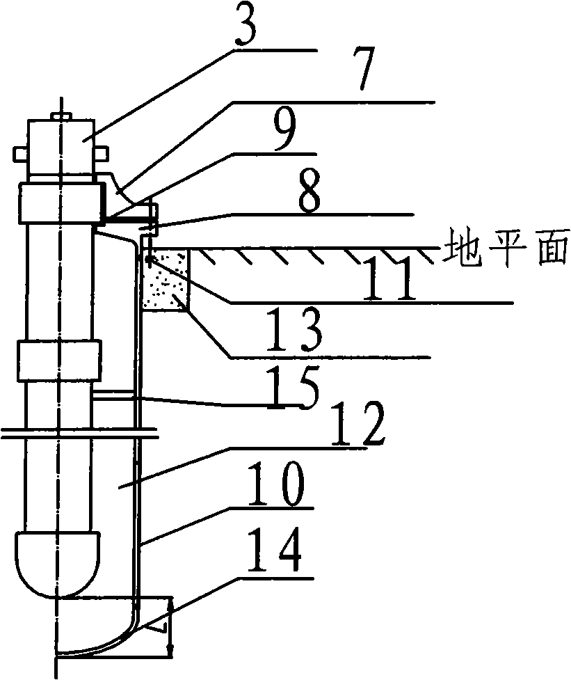
[0036] Drilling, the diameter of the well between the ground level and the hard soil layer is 1.6 times the diameter of the U-shaped barrel, the diameter of the rest of the well is 1.4 times the U-shaped barrel, and the drilling depth is the U-shaped barrel length + 20 meters (The deepening length is reserved for the wellbore collapse); firstly weld the lower head and the outer wellbore body, and then weld multiple outer wellbore bodies in turn to form a U-shaped body and sink it into the well. The uppermost end of the cylinder body is welded and connected with the flange of the special-shaped equipment on the lower side with grooves; cement is poured between the outer wall of the U-shaped cylinder body located at the ground surface and the hard soil layer and the drilling well wall to form a cementing layer and a ground surface. In the base layer, four anchor bolts are pre-buried in the base layer; the four anchor bolts are connected and fixed with the special-shaped equipment...

Embodiment 2

[0038] Drilling, the diameter of the well between the ground level and the hard soil layer is 1.8 times the diameter of the U-shaped barrel, the diameter of the rest of the drilling is 1.4 times the U-shaped barrel, and the drilling depth is the U-shaped barrel length + 20 meters (The deepening length is reserved for the wellbore collapse); firstly weld the lower head and the outer wellbore body, and then weld multiple outer wellbore bodies in turn to form a U-shaped body and sink it into the well. The uppermost end of the cylinder body is welded and connected with the flange of the special-shaped equipment on the lower side with grooves; cement is poured between the outer wall of the U-shaped cylinder body located at the ground surface and the hard soil layer and the drilling well wall to form a cementing layer and a ground surface. In the base layer, four anchor bolts are pre-buried in the base layer; the four anchor bolts are connected and fixed with the special-shaped equip...

Embodiment 3

[0040] Drilling, the diameter of the well between the ground level and the hard soil layer is 1.7 times the diameter of the U-shaped barrel, the diameter of the rest of the drilling is 1.4 times the U-shaped barrel, and the drilling depth is the U-shaped barrel length + 20 meters (The deepening length is reserved for the wellbore collapse); firstly weld the lower head and the outer wellbore body, and then weld multiple outer wellbore bodies in turn to form a U-shaped body and sink it into the well. The uppermost end of the cylinder body is welded and connected with the flange of the special-shaped equipment on the lower side with grooves; cement is poured between the outer wall of the U-shaped cylinder body located at the ground surface and the hard soil layer and the drilling well wall to form a cementing layer and a ground surface. In the base layer, four anchor bolts are pre-buried in the base layer; the four anchor bolts are connected and fixed with the special-shaped equip...


PUM


Abstract

The invention discloses an installation method of a double-walled sleeve suspended type high pressure gas underground gas storage well, and a structure thereof, wherein, the method comprises the following steps: well drilling is carried out; an outer mineshaft body is welded and sunk into the drilled well, the upmost end of the outer mineshaft body is connected with a lower-side heteromorphic equipment flange with a groove in a welding way; cement is injected to form a well cementation layer and a groundwork layer, and the groundwork layer is pre-embedded with a plurality of anchor bolts; the anchor bolts are connected and fixed with the lower-side heteromorphic equipment flange; an internal mineshaft is installed in the outer mineshaft body; two split heteromorphic equipment flanges are compressed on the upper end face of the upmost section hoop, and then the split heteromorphic equipment flanges are clamped with the lower-side heteromorphic equipment flange by bolts; and nitrogen is introduced between the internal mineshaft and the outer mineshaft body. By adopting the device and the well cementation method, the stored gas can be prevented from leaping to the outside of the well, sinking and leakage, and the gas storage well can bear the corrosion of the outer wall of the mineshaft, thus guaranteeing the axial elongation of the gas storage well when bearing pressure.

Description

technical field [0001] The invention relates to a high-pressure gas underground gas storage well installation method and its structure. Background technique [0002] 1. Introduction of high-pressure gas underground gas storage wells [0003] High-pressure gas underground gas storage well is also called CNG gas storage well. Forgings) are connected with the top cover, and 98% of the well body is buried about 100 meters to 200 meters underground to form a single-wall wellbore pressure vessel for storing compressed natural gas. Gas underground storage wells. [0004] The design of the high-pressure gas underground gas storage well has a nominal pressure of 25MPa and a design temperature of room temperature. [0005] Underground gas storage wells for high-pressure gas are new in the CNG industry, and drilling and building CNG gas storage wells is also a new technology. Compared with the same gas storage cylinder group, long tube CNG cylinder and spherical gas storage tank, C...

Claims


Application Information

Patent Timeline
IPC IPC(8): E21F17/16B65G5/00
Inventor 王世来牛卫飞
Owner TIANJIN SPECIAL EQUIP INSPECTION INST
Why Eureka
Try Eureka