Ultra-high pressure three-plunger pump

A plunger pump, ultra-high pressure technology, applied in pump components, variable displacement pump components, components of pumping devices for elastic fluids, etc., can solve problems such as poor sealing, difficult assembly and repeated positioning, and achieve excellent High elasticity, high impact strength and low flow resistance

Inactive Publication Date: 2009-04-08
黄山泰安达机电科技有限公司
View PDF0 Cites 7 Cited by
  • Summary
  • Abstract
  • Description
  • Claims
  • Application Information

AI Technical Summary

Problems solved by technology

Solve the problems of poor sealing and difficult assembly and repeated positioning in ultra-high pressure three-piston pumps

Method used


Image

  • Ultra-high pressure three-plunger pump
  • Ultra-high pressure three-plunger pump
  • Ultra-high pressure three-plunger pump

Examples


Embodiment Construction

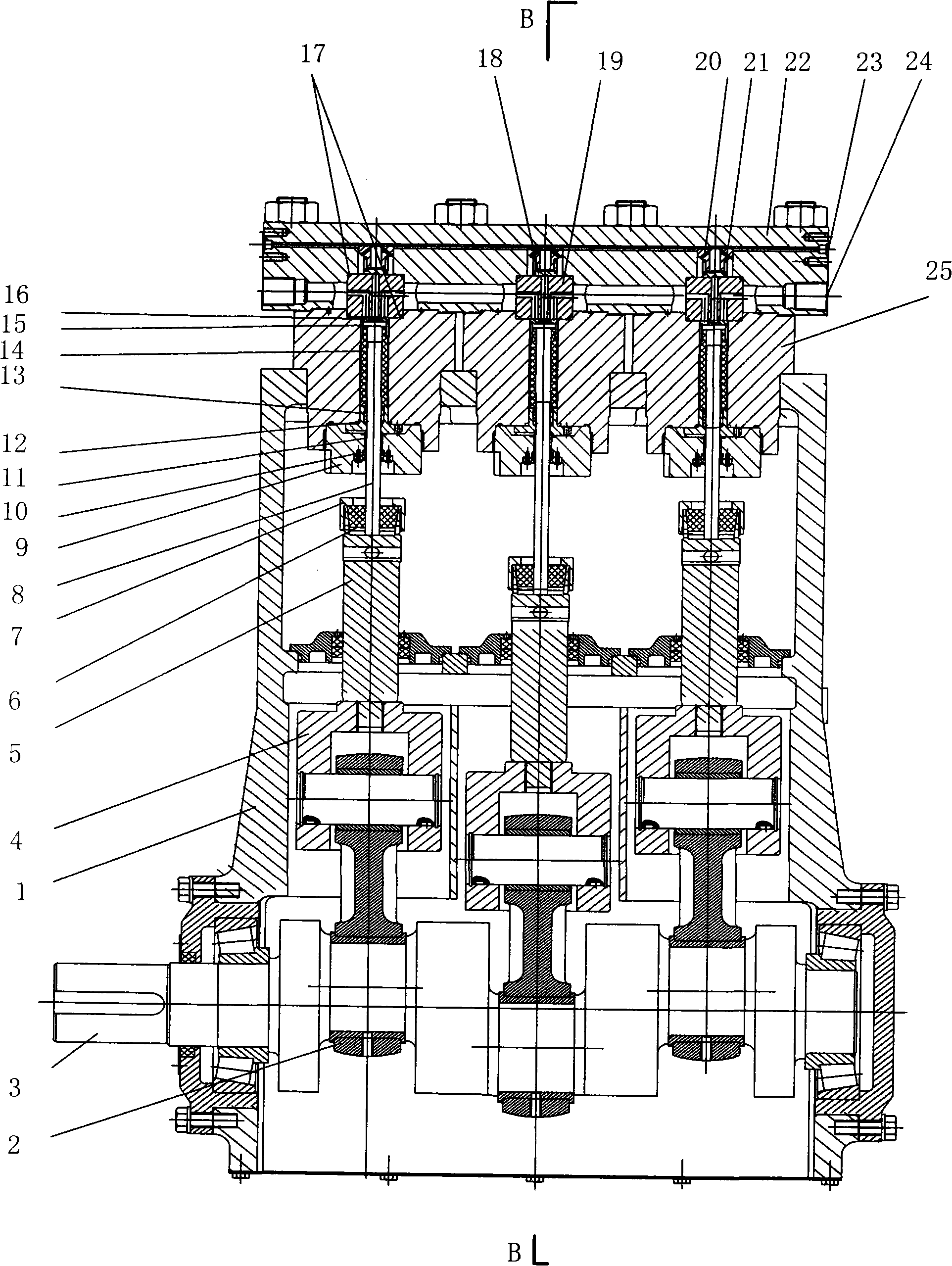
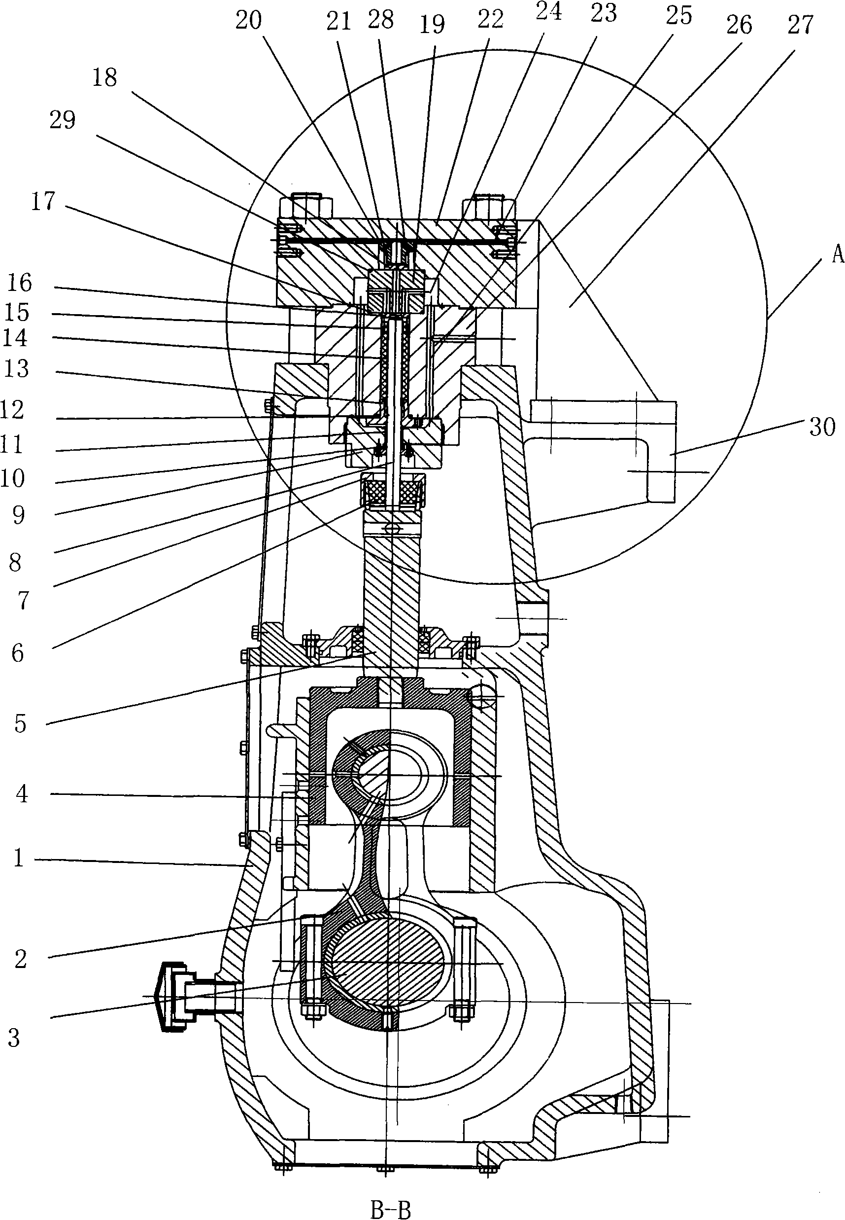
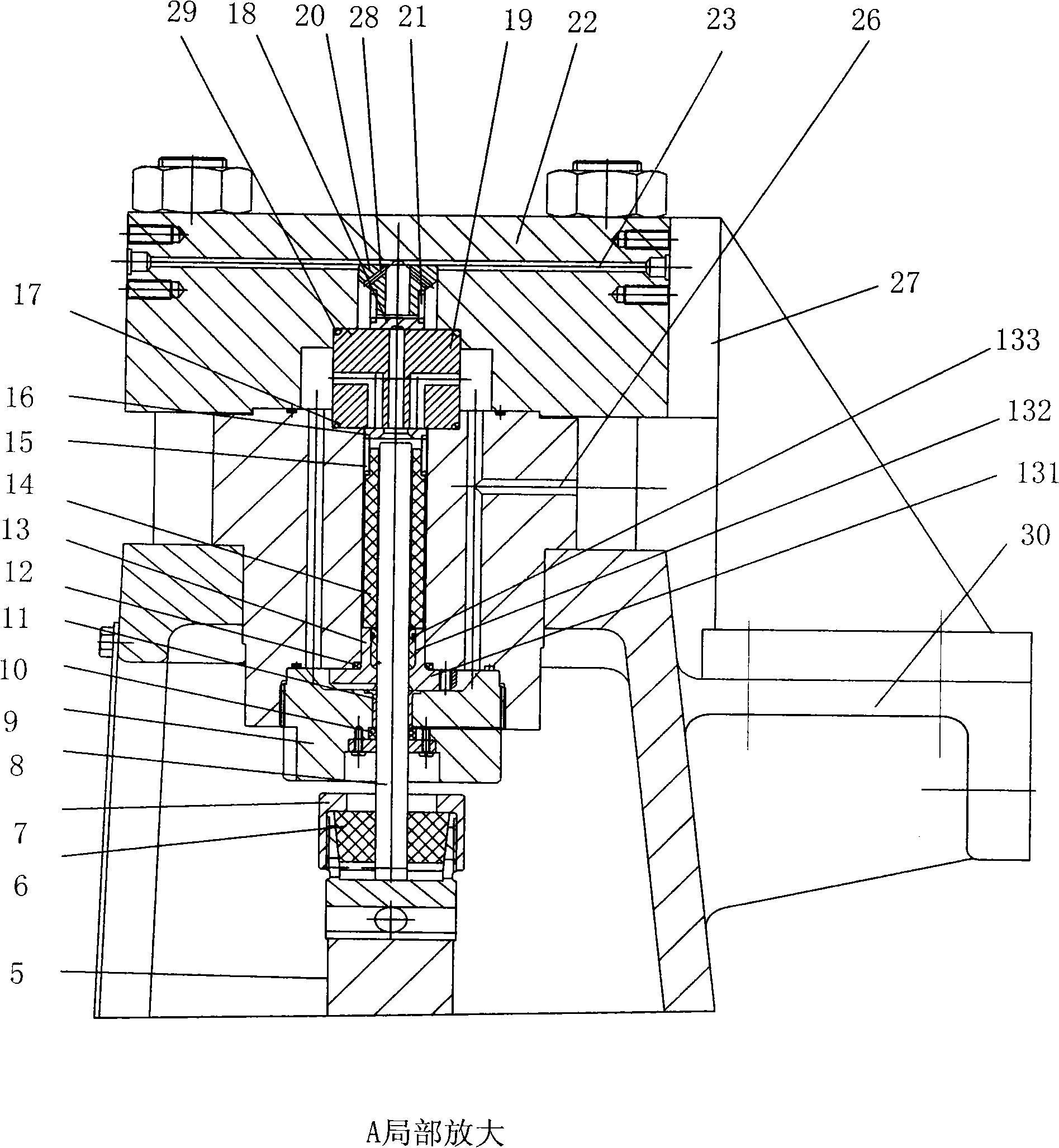
[0036] Such as figure 1 , 2, Shown in 3 and 4, an ultra-high pressure three-piston pump includes a fuselage 1, a crankshaft-connecting rod type power transmission device arranged in the fuselage and a hydraulic end generating high pressure. The crankshaft-link type power transmission device includes a crankshaft 3 , a connecting rod 2 , a crosshead 4 , an intermediate rod 5 , an elastic jacket 6 , and a pressure cap 7 . The hydraulic end includes a pump body 22, a pump cylinder 26, a plunger 8 and a sealing box 9; between the pump cylinder 26 and the pump body 22 there are also a pilot valve 20, a liquid discharge spring 21, and a discharge valve in sequence. 18, valve seat 19, suction valve 16, liquid inlet spring 15. The pump body 22 is provided with a low-pressure water inlet channel 24 and a high-pressure water outlet channel 23 . The pump cylinder 26 is provided with a cooling water channel 25 . A plunger sleeve 14 is arranged between the pump cylinder 26 and the plun...


PUM


Abstract

The invention relates to an ultrahigh pressure triple plunger pump, comprising a machine body, a crank shaft connecting rod type power transmission device and a fluid end generating high pressure. The fluid end comprises a pump body, a pump cylinder, a plunger and a sealing box body. A guide valve, a drainage spring, a discharge valve, a valve seat, an inlet valve and an intake spring are arranged in series between the pump cylinder and the pump body. The pump body is provided with a low-pressure water inlet flow channel and a high-pressure water outlet flow channel. The pump cylinder is provided with a condensed water flow channel. A plunger sleeve is arranged between the pump cylinder and the plunger. A sealing component is arranged between the pump cylinder and the sealing box body. A bearing and a first sealing ring are arranged in the sealing box body. A second sealing ring is arranged between the pump cylinder and the sealing component. Two ends of the valve seat are provided with a third sealing ring and a fourth sealing ring. The pump body is of integral type structure. A group of guide holes with the function of buffering are uniformly distributed at the circumference of the guide valve. The condensed water flow channel is communicated with the low-pressure water inlet flow channel on the pump body. A bracket and sliding block type resetting structure is arranged outside the pump body. As a multi-sealing and resetting structure is adopted, the problems that the sealing of the pump is not good and the assembly and the resetting are difficult are solved.

Description

technical field [0001] The invention relates to a plunger pump, in particular to an ultra-high pressure three-piston pump. Background technique [0002] The high-pressure three-piston pump mainly includes a fuselage, a crankshaft-connecting rod power transmission device installed in the fuselage, and a hydraulic end that generates high pressure. At present, there are many domestic manufacturers of plunger pumps, and the maximum rated working pressure can only be limited within 150Mpa, and the plunger pumps with pressure higher than 150Mpa can only rely on imports. The fundamental reason is that the breakthrough in ultra-high pressure technology is a big technical bottleneck. The main reason is that the sealing structure at the liquid end plunger of an ordinary three-plunger pump mostly adopts the traditional contact type seal, and there are no more than two types of methods: compression type seal and self-sealing type seal. The compression type seal is also called the fill...

Claims


Application Information

Patent Timeline
Patent Type & Authority Applications(China)
IPC IPC(8): F04B53/02F04B53/08F04B53/18F04B53/00
Inventor 柯伯成柯伯留柯宝来汪丽君鲍际辉柯仲政蒋辉东王坚耿焕庚
Owner 黄山泰安达机电科技有限公司
Why Eureka
Try Eureka