Double-step jigsaw puzzle scanner of scanning probe microscope

A technology for scanning probes and microscopes, applied in the field of scanning probe microscopes, can solve the problems of unfavorable microscope extreme conditions, increased interference, and vibration, etc., and achieve the effect of increasing structural complexity and compact structure

Inactive Publication Date: 2009-04-08
UNIV OF SCI & TECH OF CHINA
View PDF0 Cites 11 Cited by
  • Summary
  • Abstract
  • Description
  • Claims
  • Application Information

AI Technical Summary

Problems solved by technology

However, this method does not work for scanning force microscopes (such as: atomic force microscopes, magnetic force microscopes, etc.) that rely on vibrating probe microrods to measure force imaging, because both the probe and the sample require inertial sliding steps (a longitudinal, A horizontal direction), is not fixed, and our measurement data show that: the vibration of the probe micro-rod can shake the slider it is on (the slider has recoil), resulting in the vibration of the probe micro-rod being affected, or even no vibration
Other major drawbacks of this method include: the use of dual piezoelectric scanning tubes increases the complexity of the microscope, which is not conducive to the extreme conditioning of the microscope, and the increase in signals also leads to increased mutual interference, which is not conducive to the accurate measurement of weak imaging signals
[0003] According to our investigation, there is still no scanning probe microscope in the world that can perform atomic-resolution imaging search without gaps in the millimeter range ( That is, the imaging everywhere can be assembled into a complete large picture)

Method used


Image

  • Double-step jigsaw puzzle scanner of scanning probe microscope
  • Double-step jigsaw puzzle scanner of scanning probe microscope
  • Double-step jigsaw puzzle scanner of scanning probe microscope

Examples


Embodiment 1

[0034] Example 1: Basic Scanning Probe Microscope Dual-step Mosaic Scanner

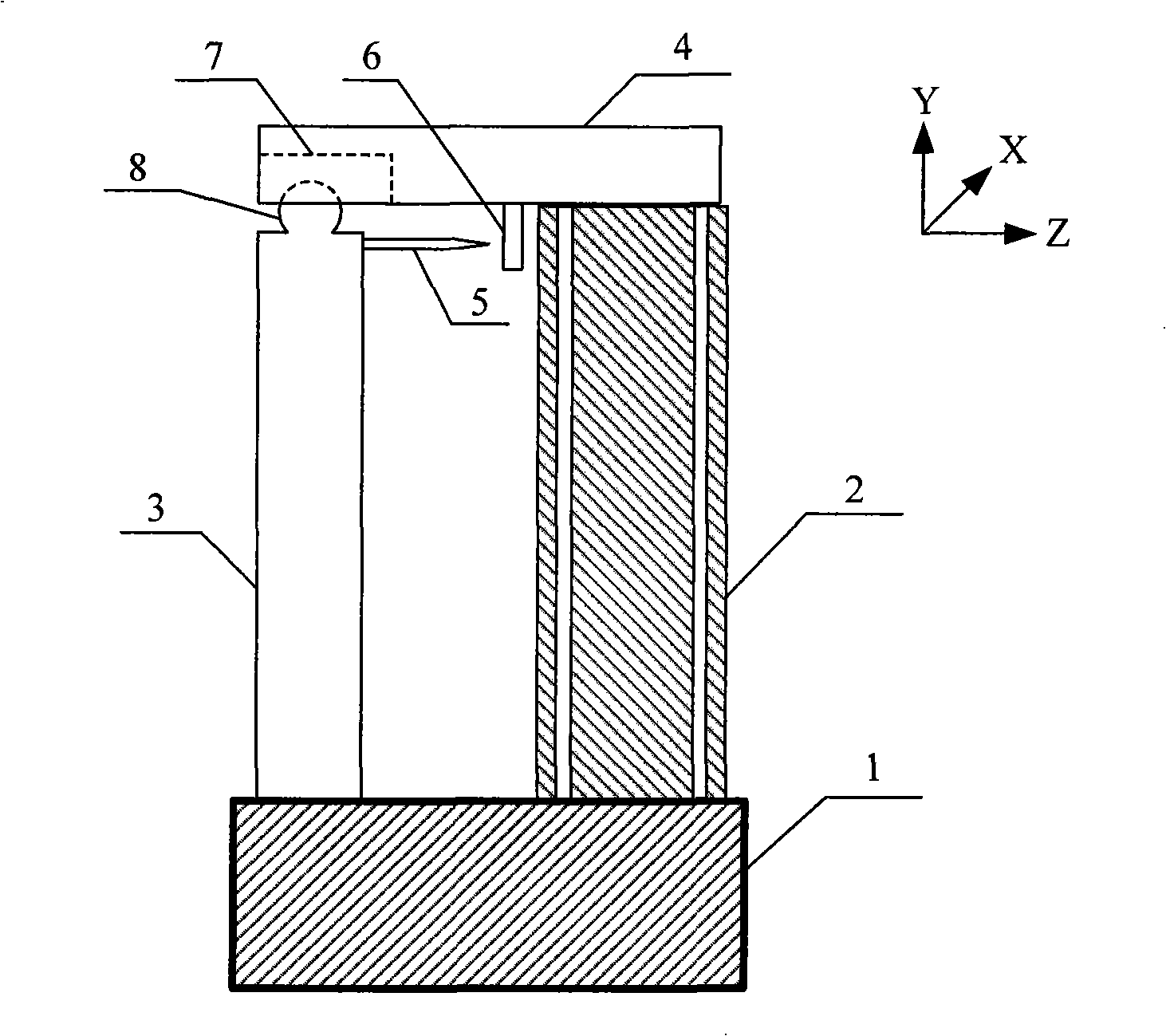
[0035] The structural schematic diagram of the double-stepping mosaic scanner of the basic scanning probe microscope of the present invention is shown in figure 2 , including a base 1, a piezoelectric scanning tube 2, a column 3, and a slider 4, wherein the piezoelectric scanning tube 2 and the column 3 stand side by side and are fixed on the base 1, and the arrangement direction thereof is set as the Z direction, The slider 4 is arranged on the top of the piezoelectric scanning tube 2 and the column 3, between the slider 4 and the column 3 there is a groove 7 along the Z direction and a convex top 8 on the notch or the surface of the groove. direction, the maximum static friction force between the slider 4 and the column 3 is smaller than the maximum static friction force between the slider 4 and the piezoelectric scanning tube 2 .

[0036] The working principle of this embodiment is as follows:

...

Embodiment 2

[0041] Example 2: Scanning Probe Microscope with Electrodes Along the Z Direction Double-step Mosaic Scanner

[0042] In the above-mentioned Embodiment 1, the piezoelectric scanning tube 2 must be able to be controlled to bend in the Z direction and the X direction. Arbitrary setting of the electrode direction of the piezoelectric scanning tube 2 can make the piezoelectric scanning tube 2 capable of being controlled to bend in the Z direction and the X direction, but the cooperation between the voltage signals on each electrode becomes complicated. The simplest electrode direction setting is: the arrangement direction of the piezoelectric scanning tube 2 and the column 3 is the same as the scanning bending direction of two opposite electrodes among the four external electrodes of the piezoelectric scanning tube.

Embodiment 3

[0043] Example 3: Scanning Probe Microscopy Dual Stepping and Jigsaw Scanner Containing Spacers

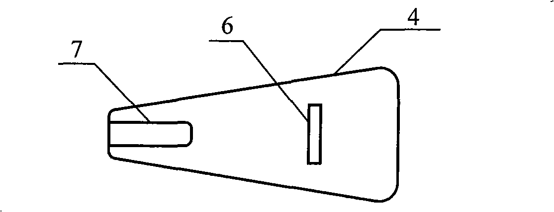
[0044] In the above embodiment, in order to make the maximum static friction force between the slider 4 and the column 3 smaller than the maximum static friction force between the slider 4 and the piezoelectric scanning tube 2, the piezoelectric scanning tube 2 and the slider according to the present invention Spacers 9 can be added between blocks 4 (see image 3 ).


PUM


Abstract

The invention relates to a double-step image-piecing scanner used for a scanning probe microscope and belongs to the scanning probe microscope field. The invention comprises a seat (1), a piezoelectric scanning tube (1), a sliding block (4) and a vertical column (3). The piezoelectric scanning tube and the vertical column are arranged in series and fixed on the seat; the sliding block is arranged on the top of the piezoelectric scanning tube and the vertical column; a groove (7) and a projective top (8) clinging to the groove notch or surface are arranged between the sliding block and the vertical column; the groove is arranged on the arranging direction of the piezoelectric scanning tube and the vertical column and the maximum static friction force on the direction between the sliding block and the vertical column is less than that between the sliding block and the piezoelectric scanning tube. Without complicated structure, the invention just adopts one piezoelectric scanning tube to lead the probe to carry out the atomic-resolution imaging search above millimeter range and without recoil; the structure is simple and compact so as to bring convenience for the application in rigid conditions; and the interferences between control signals can be largely reduced and the temperature drift can be reduced and the stability can be enhanced.

Description

technical field [0001] The invention relates to a scanning probe microscope, in particular to an atomic precision scanner driven by a single piezoelectric scanning tube, stepping in two directions and capable of mosaic search for the scanning probe microscope. Background technique [0002] The scanning probe microscope is the only atomic resolution microscope that can work under a variety of extreme conditions, and its ability to manipulate atoms is unmatched by any other tool, which makes it quickly develop into a hallmark of nanotechnology today, but it is extremely important in the following In the field of nanoscience research, the above advantages are useless: perform atomic imaging or atomic manipulation on a specific microscopic area (such as specific defects, impurity atoms, or specified microdevices or molecules) on the sample to be tested, because it is necessary to complete this For this task, it is necessary to conduct a gapless minesweeping search at the sample ...

Claims


Application Information

Patent Timeline
IPC IPC(8): G01N13/10
Inventor 庞宗强王霁晖陆轻铀
Owner UNIV OF SCI & TECH OF CHINA
Why Eureka
Try Eureka