Buoyancy ascending-descending water decanter and implementation method thereof

A realization method, lift-type technology, applied in chemical instruments and methods, biological water/sewage treatment, water/sludge/sewage treatment, etc., can solve problems such as complex mechanical lifting devices, power consumption, misoperation, etc., and achieve increased Effects of Structural Complexity

Inactive Publication Date: 2013-05-01
CHENGDU UNIV OF INFORMATION TECH
View PDF4 Cites 4 Cited by
  • Summary
  • Abstract
  • Description
  • Claims
  • Application Information

AI Technical Summary

Problems solved by technology

[0005] 1. The work needs to consume electricity, which is not energy-saving and environmentally friendly;
[0006] 2. The mechanical lifting device is complicated, resulting in high manufacturing and maintenance costs of the mechanical decanter;
[0007] 3. The liquid level will continue to drop during the decanting process, and it is difficult to keep the immersion depth of the weir of the decanting tank under the liquid level of the reaction tank constant. The operation is cumbersome and the realization process is complicated.
[0011] 3. Need to rely on spring force, mechanical force and sealing friction force, not only the structure is complicated, it is easy to cause misoperation, but also the valve failure rate is high, not only troublesome to maintain, but also seriously affect the normal use of the decanter

Method used


Image

  • Buoyancy ascending-descending water decanter and implementation method thereof
  • Buoyancy ascending-descending water decanter and implementation method thereof
  • Buoyancy ascending-descending water decanter and implementation method thereof

Examples


Embodiment 1

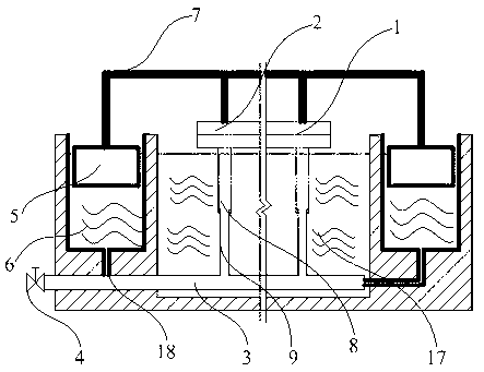
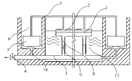
[0057] The buoyancy lifting decanter is mainly composed of the following three parts: the decanting tank, located above the reaction tank, is the direct part of the decanting operation; the floating lifting mechanism is directly connected with the decanting tank to realize the executive mechanism of the decanting tank; the drainage System, during decanting operation, the supernatant liquid in the reaction tank is finally discharged by the drainage system.

[0058] In order to enable those skilled in the art to have a clearer understanding of the above components, it will be described in detail below in conjunction with the accompanying drawings, as figure 1 , 2 As shown, the structure of the decanting tank 2 is similar to that of the existing decanting tank, and a decanting weir 1 is provided on it. During the decanting operation, the supernatant liquid of the reaction tank 17 is introduced into the decanting tank 2 through the decanting weir 1.

[0059] Floating lifting mech...

Embodiment 2

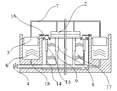
[0065] Such as image 3 , 4 As shown, the difference between this embodiment and Embodiment 1 is that, on the basis of the structure of Embodiment 1, there is also a replenishment valve connected with the drain main pipe 3, and the replenishment valve includes a telescopic replenishment pipe, a floating ring 10, a decanter Water plate 12, floating spool 13 and limit plate 16 five parts.

[0066] The telescopic water replenishment pipe communicates with the drainage main pipe 3, and its structure is similar to that of the telescopic drainage branch pipe. Composition, the connection method of the water replenishment branch pipe 14 and the water replenishment casing 15 is an existing mature technology, therefore, this embodiment will not repeat them.

[0067] The structure of the floating ring 10 is as Figure 5 , 6 As shown, it has a certain thickness, and the decanting plate 12 is arranged at the lower end of the floating ring 10, and the two are connected by several strip ...


PUM


Abstract

The invention discloses a buoyancy ascending-descending water decanter, which is mainly used for solving the problems of complex structure, easiness in damaging, inconvenience in installing and maintaining, high cost and the like existing in the conventional water decanter. The buoyancy ascending-descending water decanter comprises a water decanting groove, a main drain, a drain valve and a buoyancy ascending-descending mechanism, wherein water decanting groove is provided with a water decanting weir crest; the main drain is connected with the water decanting groove through a telescopic branch drain; the drain valve is arranged at the water outlet of the main drain; the buoyancy ascending-descending mechanism is used for driving the water decanting groove to ascend and descend through buoyancy, and comprises a buoyancy tank pond inside which a buoyancy tank floats; the buoyancy tank is fixedly connected with the water descanting groove through a bracket, and moves synchronously with the water descanting groove; and the bottom of the buoyancy tank pond is communicated with the main drain. On the basis of the structure, the invention further discloses an implementation method of the buoyancy ascending-descending water decanter. The buoyancy ascending-descending water decanter has the advantages of simple structure, no quick-wear part, high cost performance and suitability for popularizing and applying.

Description

technical field [0001] The invention relates to a water decanter used for sewage treatment, in particular to a buoyancy-lifting water decanter and its realization method. Background technique [0002] The SBR process adopts batch reaction, and the water intake, reaction, sedimentation, and drainage are completed in the same pool, without the need for secondary sedimentation tanks and sludge return equipment. It is widely used in papermaking, alcohol, dyes, pesticides, leather, viscose, monosodium glutamate, In the treatment of industrial wastewater (waste liquid) in industries such as sugar refining. When using SBR process or similar process to treat sewage, it is necessary to use a decanter to discharge the supernatant of the liquid in the reaction tank after the static sedimentation stage out of the tank. The decanter has the function of decanting the clarified water (supernatant liquid) from the surface of the static reaction tank without stirring the sediment and ensuri...

Claims


Application Information

Patent Timeline
IPC IPC(8): C02F3/12
CPCY02W10/10
Inventor 申小颂
Owner CHENGDU UNIV OF INFORMATION TECH
Why Eureka
Try Eureka