
Miniature direct-drive permanent magnet synchronous aerogenerator and its small-sized wind power generation system

A wind power generation system, wind power generator technology, applied in the direction of multi-output synchronous motors, synchronous motors with stationary armatures and rotating magnets, wind power generation, etc.

Inactive Publication Date: 2012-05-02
鹤山市信利带钢有限公司
View PDF7 Cites 0 Cited by
  • Summary
  • Abstract
  • Description
  • Claims
  • Application Information

AI Technical Summary

Problems solved by technology

[0006] In addition, in the patent literature with the publication number CN101017998A and the publication date being August 15, 2007, a direct-drive excitation wind force using a double-stator structure is disclosed. Generators use a double-stator structure to increase power density and capture the maximum wind energy. Although a certain use effect is achieved, the fan with this structure can only simply increase the power density, and it cannot work under the condition of a wide range of wind speed changes. Stable, and in the case of simply increasing the power density, the manufacturing cost is too high

Method used

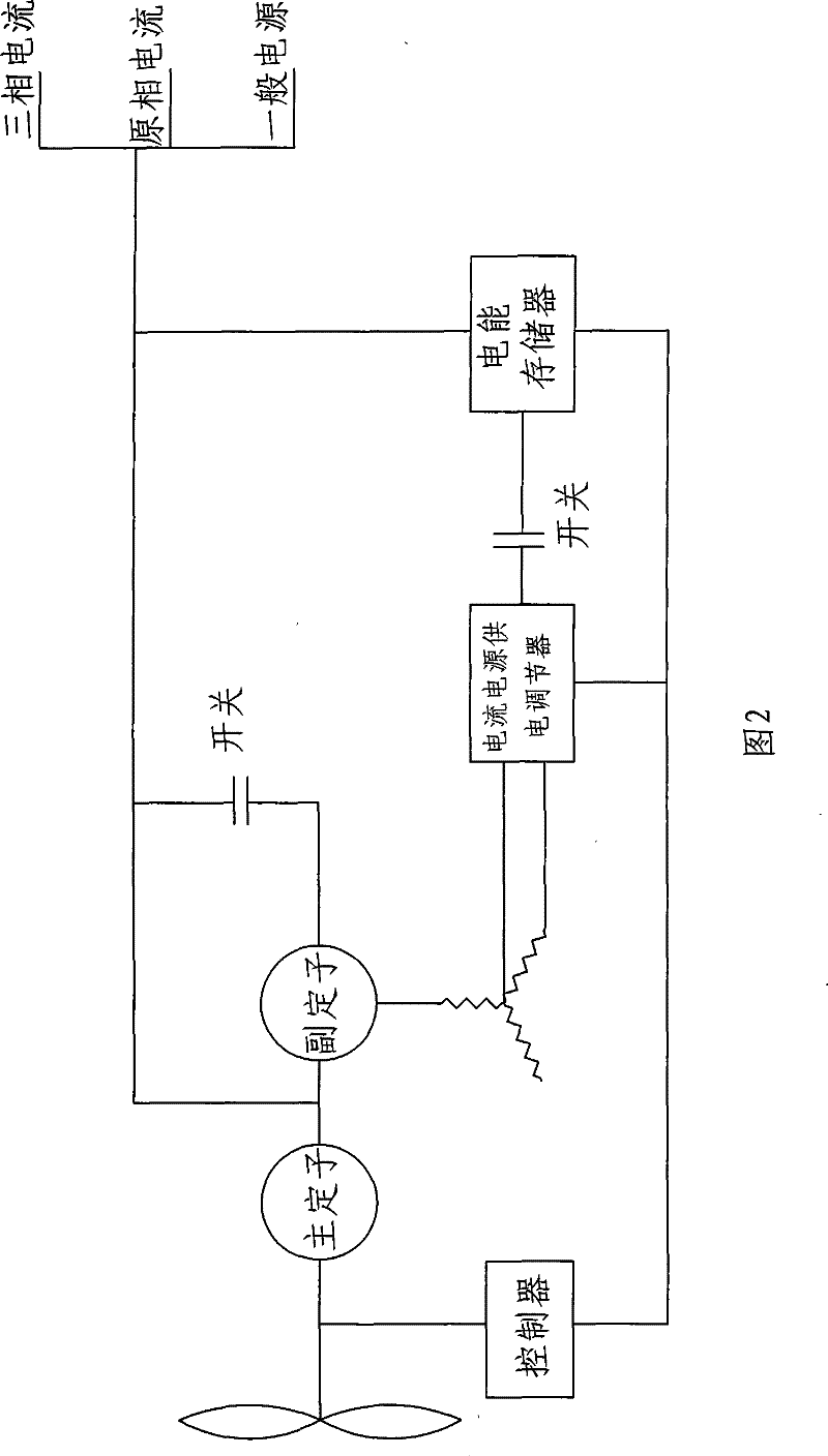

Image

  • Miniature direct-drive permanent magnet synchronous aerogenerator and its small-sized wind power generation system
  • Miniature direct-drive permanent magnet synchronous aerogenerator and its small-sized wind power generation system
  • Miniature direct-drive permanent magnet synchronous aerogenerator and its small-sized wind power generation system

Examples


Embodiment Construction

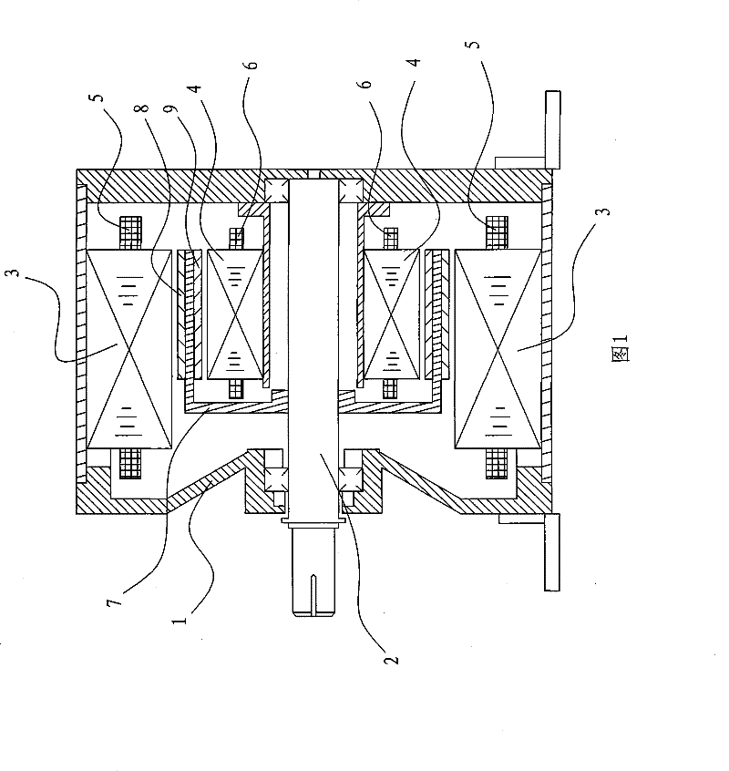
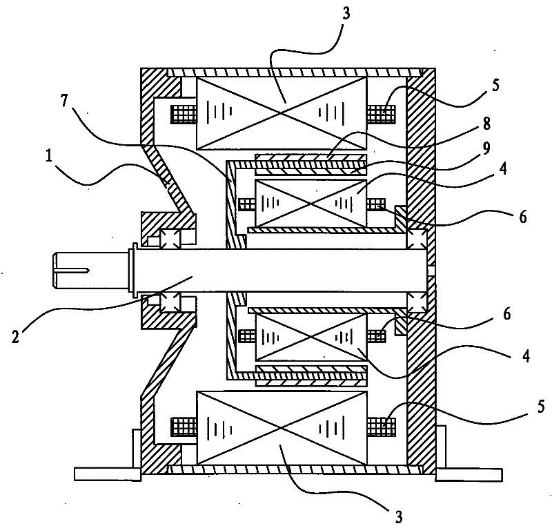
[0020] refer to figure 1 , a small direct-drive permanent magnet synchronous wind power generator of the present invention, including a casing 1, the casing 1 is installed with a rotating shaft 2 through bearings, a main stator 3 and an auxiliary stator 4 are installed and fixed in the casing 1, and there are 3 sets of main stators On the periphery of the auxiliary stator 4, the main stator 3 and the auxiliary stator 4 have a main stator winding 5 and an auxiliary stator winding 6 respectively, and a rotor 7 connected to the rotating shaft 2 is arranged between the main stator 3 and the auxiliary stator 4, and the rotor 7 There are outer permanent magnets 8 and inner permanent magnets 9 corresponding to the main stator 3 and the auxiliary stator 4 respectively, and one phase winding of the auxiliary stator winding 6 is connected to a DC power supply adjustment control terminal.

[0021] Further, as a preferred embodiment of the present invention, the motor stator and rotor ha...


PUM


Abstract

The invention discloses a small-sized direct-drive permanent magnetism synchronous aerogenerator and a generating system thereof. The aerogenerator comprises a shell which is supported with a rotating shaft by a bearing; a main stator and an auxiliary stator are fixed in the shell, and the main stator is sheathed on the circumstance of the auxiliary stator; a main stator winding and an auxiliary stator winding are arranged respectively on the main stator and the auxiliary stator, and a rotor which is connected with the rotating shaft is arranged between the main stator and the auxiliary stator; an outer permanent magnet and an inner permanent magnet which are corresponding to the positions of the main stator and the auxiliary stator are respectively arranged on the rotor; one group of winding in the auxiliary stator winding is connected with a direct current power supplying regulation control end. The generating system also comprises an electrical energy memorizer, a direct current power supplying adjustor, a controller and the like, the aerogenerator can adopt a method of power regulation and energy compensation to keep the stability of the wind energy generating system, thus leading the working efficiency of the whole generating system to be effectively improved.

Description

technical field [0001] The invention relates to a wind power generator and a wind power generation system, in particular to a small wind power generator and a wind power generation system. Background technique [0002] Wind power is one of the fastest-growing renewable energy technologies. There are commonly used AC asynchronous generators and double-fed asynchronous generators. In wind power systems, gears need to be increased. For double-fed asynchronous generators, carbon brushes and sliding The manufacturing cost of this kind of wind power system is high, the reliability is poor, and the noise pollution is very serious. [0003] Gearbox-less, direct drive, and brushless have attracted people's attention. The new wind power generation system scheme is a direct-drive multi-pole permanent magnet synchronous generator with variable speed operation, pitch adjustment, low speed, high efficiency, and high power factor. become the current research and development hotspot. [0...

Claims


Application Information

Patent Timeline
Patent Type & Authority Patents(China)
IPC IPC(8): H02K16/00H02K16/04H02K21/12H02K21/48H02K1/27H02K1/16H02K3/12
CPCY02E10/725Y02E10/72
Inventor 徐继鸿吴金华赵少俊
Owner 鹤山市信利带钢有限公司
Learn More