Transmission gear for control spindle of cam automatic lathe

A technology of automatic lathes and transmission devices, which is applied in the direction of automatic lathes/semi-automatic lathes, feeding devices, turning equipment, etc., and can solve the problems of reduced precision of distribution shafts, difficulty in ensuring the precision of processed parts, and large fit gaps, etc.

Inactive Publication Date: 2009-04-15
刘军
View PDF0 Cites 1 Cited by
  • Summary
  • Abstract
  • Description
  • Claims
  • Application Information

AI Technical Summary

Problems solved by technology

[0002] The structure of the traditional technology is that copper tiles are installed between the distribution shaft 1 and the holes of the distribution shaft brackets 2, 12, and 14, and the rotation directly generates friction. After a long time, the copper tiles

Method used


Image

  • Transmission gear for control spindle of cam automatic lathe
  • Transmission gear for control spindle of cam automatic lathe

Examples


Embodiment Construction

[0006] specific implementation plan

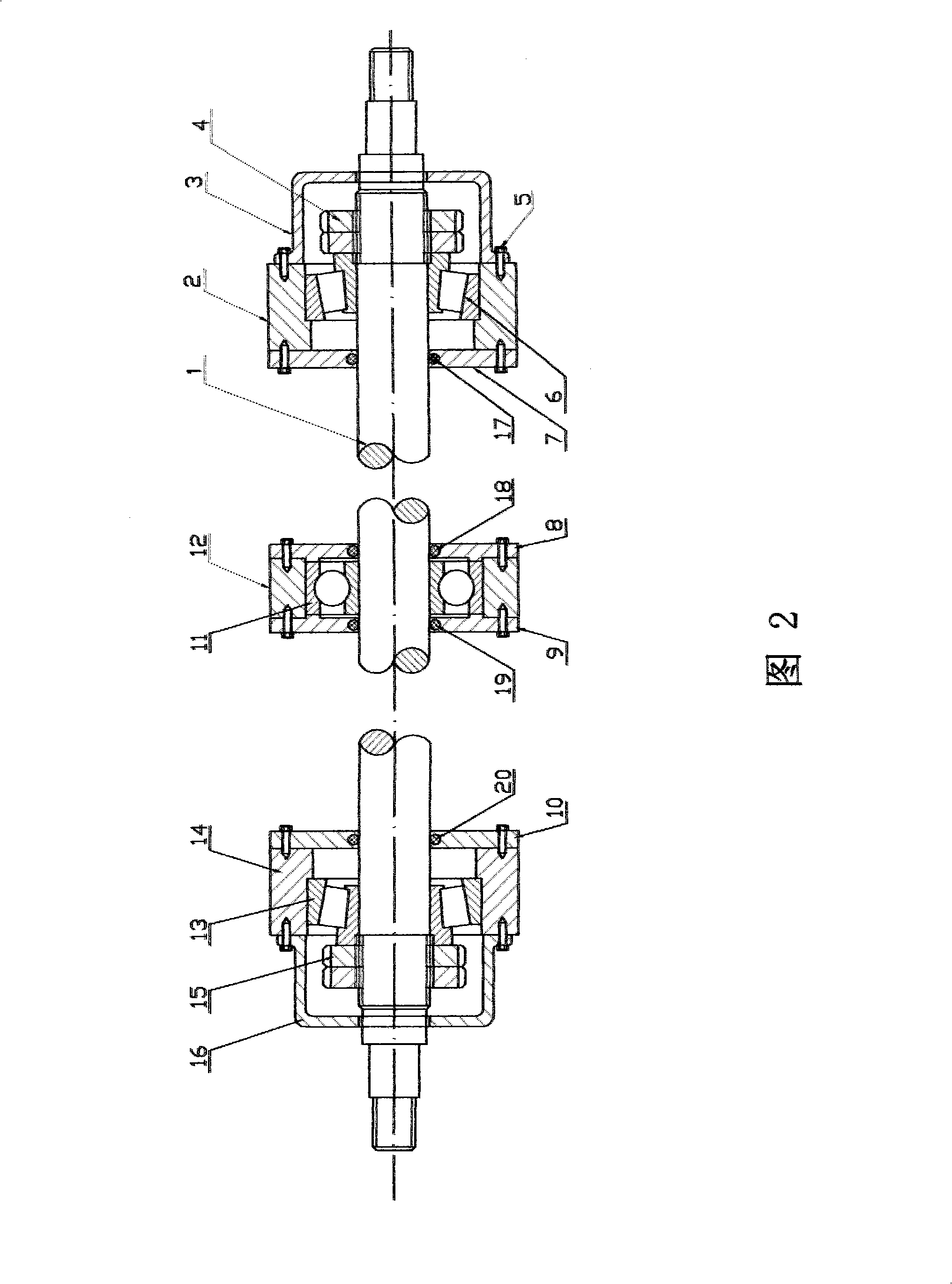
[0007] 1. The current utilization method is: refer to Figure 2, according to the design requirements of the drawing of the distribution shaft 1, A. After quenching and tempering the round steel, use the lathe to make the size, B. Mill the keyway, C. Heat treatment, D. Grinding outer diameter.

[0008] 2. The current utilization method is, referring to Fig. 2, according to the drawing design requirements of distribution shaft brackets 2, 12, 14, A, making the appearance with cast iron casting, milling, and wire cutting, B, using a lathe, boring machine, and wire cutting The processing is used for the holes of device bearings 6,11,13.

[0009] 3. The method currently utilized is, referring to Fig. 2, according to the design requirements of the drawings of the dust cover 3, 16, A, using metal materials, car-making its external shape and inner hole cavity, B, drilling and distributing shaft frame 2 , 12, 14, the screw hole of connection, C, ...


PUM


Abstract

The invention provides a transmission device for a distributing shaft of a cam automatic lathe. A bearing 6, a bearing 11 and a bearing 13 are arranged between the distributing shaft 1 and distributing shaft brackets 2, 12 and 14, so as to improve the cutting precision of the lathe, prolong the service life of the distributing shaft, and reduce wasted working hours due to maintenance. The transmission device is characterized in that the bearing 6, the bearing 11 and the bearing 13 are arranged in holes formed by the distributing shaft 1 and the distributing shaft brackets 2, 12 and 14.

Description

technical field [0001] The invention belongs to the mechanical equipment manufacturing industry, in particular to the distribution shaft transmission device of a cam automatic lathe Background technique [0002] The structure of the traditional technology is that copper tiles are installed between the distribution shaft 1 and the holes of the distribution shaft brackets 2, 12, and 14, and the rotation directly generates friction. After a long time, the copper tiles and the distribution shaft will have an excessive fit gap due to friction. , so that the accuracy of the distribution shaft is reduced, making it difficult to ensure the accuracy of the machined parts during the operation of the equipment, and frequent maintenance. Contents of the invention [0003] The invention provides a distribution shaft transmission device for a cam automatic lathe. The device is provided with bearings 6, 11, 13 in the holes between the distribution shaft 1 and the distribution shaft brack...

Claims


Application Information

Patent Timeline
IPC IPC(8): B23Q5/34B23B19/02B23B7/00
Inventor 刘军刘东刚
Owner 刘军
Why Eureka
Try Eureka