Device for testing linearity of electro-optical modulator

An electro-optical modulator and testing device technology, applied in the direction of testing optical performance, etc., can solve the problems of fiber optic gyroscope nonlinearity, error, and no public report on measuring intensity modulators, etc., and achieves low frequency requirements and low linearity requirements. Effect

Active Publication Date: 2009-04-15
BEIJING AEROSPACE TIMES OPTICAL ELECTRONICS TECH
View PDF0 Cites 8 Cited by
  • Summary
  • Abstract
  • Description
  • Claims
  • Application Information

AI Technical Summary

Problems solved by technology

Since the feedback modulation signal applied to the Y waveguide integrated optical device is used to compensate the phase difference caused by the input rate of the fiber optic gyroscope, and the feedback modulation signal is determined according to the slope determined by the half-wave voltage of the Y waveguide integrated optical device, so the Y waveguide is required The response of the integrated optical device is linear, otherwise, when a small signal is input, the phase difference generated by the feedback modulation signal after passing through the Y waveguide integrated optical device may be different from the absolute value of the phase difference generated by the input rate of the fiber optic gyroscope, resulting in an error , this error will cause the nonlinearity of the fiber optic gyroscope at small speeds
[0003] At present, there is no public introduction of a measuring device for measuring the linearity of the Y-

Method used


Image

  • Device for testing linearity of electro-optical modulator
  • Device for testing linearity of electro-optical modulator
  • Device for testing linearity of electro-optical modulator

Examples


Embodiment Construction

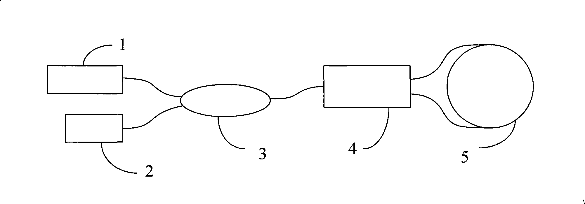
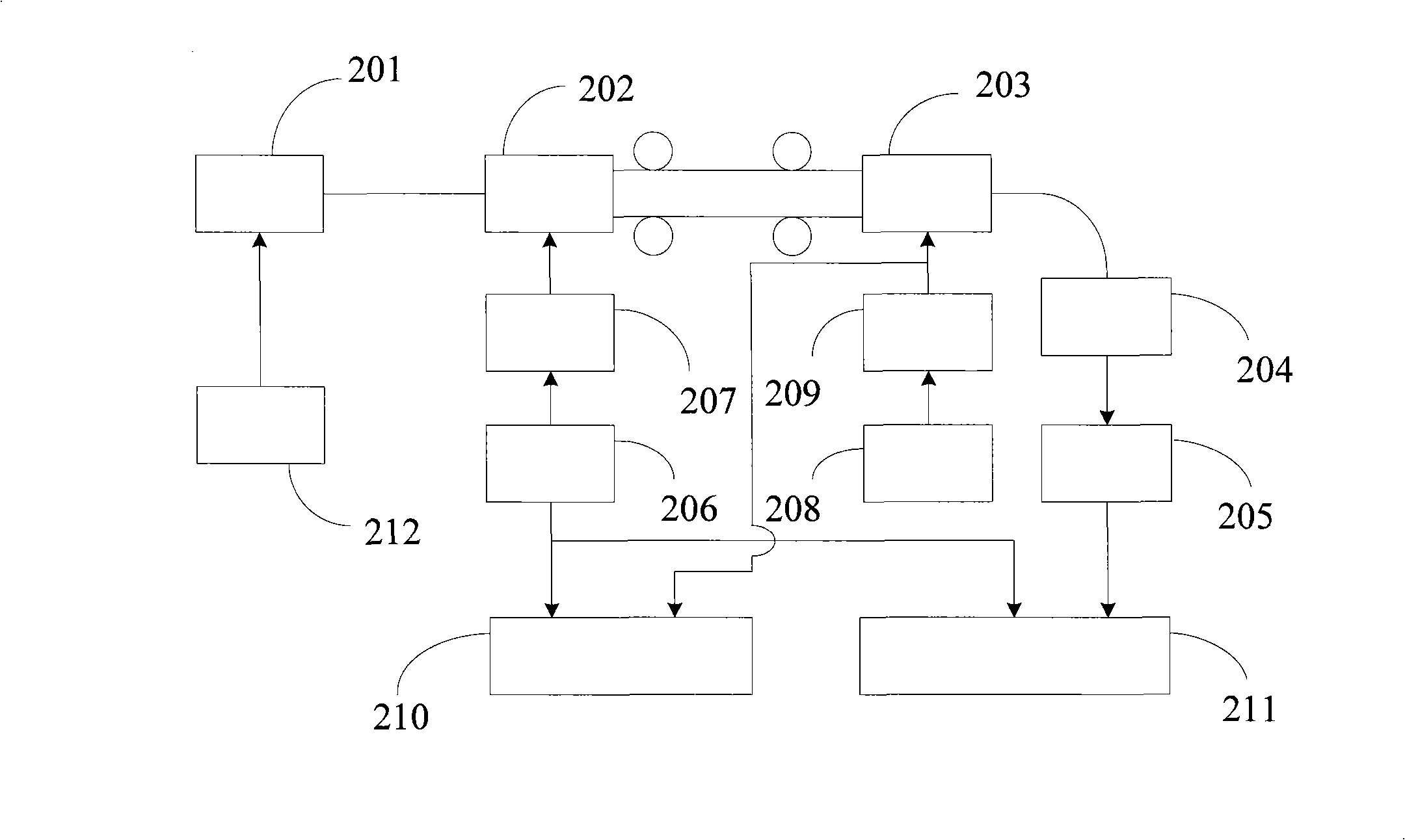
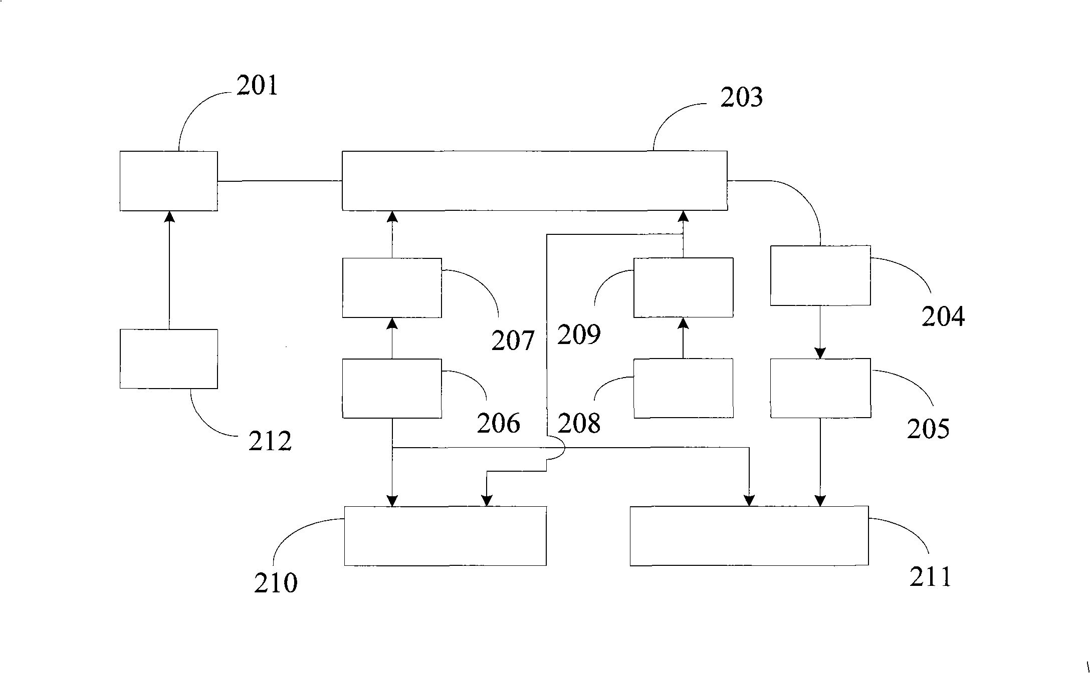
[0023] Such as figure 2 , 3 As shown, it is a structural diagram of the test device of the present invention, including a light source 201, a detector 204, a modulation signal generator 206, a test signal generator 208, a first demodulation circuit 210, and a second demodulation circuit 211; When the modulator 203 is an intensity modulator ( image 3 shown), the light wave sent by the light source 201 is sent to the electro-optic modulator 203 under test, and the modulation signal generated by the modulation signal generator 206 is respectively sent to the electro-optic modulator under test 203, the first demodulation circuit 210 and the second demodulation circuit 211 , the test signal that the test signal generator 208 produces is respectively sent into the electro-optic modulator 203 under test and the first demodulation circuit 210, and in the electro-optic modulator 203 under test, the modulation signal causes a modulation phase difference to be produced between the two...


PUM


Abstract

The invention discloses a testing device for linearity of an electro-optical modulator. If the electro-optical modulator to be tested is an intensity modulator, an optical wave from an optical source is sent to the electro-optical modulator to be tested, a modulation signal generator generates a modulation signal and sends the modulation signal to the electro-optical modulator to be tested, a first demodulator circuit and a second demodulator circuit; a test signal generator generates a test signal and sends the test signal to the electro-optical modulator to be tested and the first demodulator circuit. In the electro-optical modulator to be tested, the modulation signal causes the two optical waves to generate modulation phase difference, the test signal causes the two optical waves to generate test phase difference, the two optical waves are interfered and sent to a detector, and sent to the second demodulation circuit after photoelectric conversion, the first demodulation circuit obtains the size of the test signal, and the second demodulation circuit obtains the test phase difference; if the electro-optical modulator to be tested is a Y-waveguide integrated optical device, the optical wave of the optical source is sent to the electro-optical modulator to be tested by an electro-optical modulator for modulation, the modulation signal from the modulation signal generator is sent to the electro-optical modulator for modulation, the test signal from the test signal generator is sent to the tested electro-optical modulator, and the other structures are not changed.

Description

technical field [0001] The invention relates to a testing device, in particular to a testing device for an electro-optic modulator. Background technique [0002] Fiber optic gyroscope is a new type of inertial device. It has no moving parts in its structure, and has the advantages of small size, low power consumption, fast start-up, large dynamic range, wide accuracy coverage, long life, high reliability, and low batch cost. There are two schemes of open-loop and closed-loop fiber optic gyroscopes. The closed-loop fiber optic gyroscope is more widely used because of its small nonlinear scale factor and high precision. The typical optical path of the closed-loop fiber optic gyroscope is as follows: figure 1 As shown in the figure, 1 is the light source, 2 is the detector, 3 is the fiber coupler, 4 is the Y waveguide integrated optical device, and 5 is the fiber coil. Y-waveguide integrated optical devices are used as implementation devices for bias modulation and feedback c...

Claims


Application Information

Patent Timeline
IPC IPC(8): G01M11/02
Inventor 王学锋王巍于海成高峰王军龙
Owner BEIJING AEROSPACE TIMES OPTICAL ELECTRONICS TECH
Why Eureka
Try Eureka