Drive circuit for laser

A technology for driving circuits and lasers, used in lasers, laser parts, semiconductor lasers, etc., can solve the problems of laser wavelength drift, overshoot, and system work confusion.

Active Publication Date: 2009-04-15
APAT OPTOELECTRONICS COMPONENTS
View PDF0 Cites 18 Cited by
  • Summary
  • Abstract
  • Description
  • Claims
  • Application Information

AI Technical Summary

Problems solved by technology

After testing, the wavelength of the laser has a large drift at this moment, and it exceeds the normal channel spacing range, which will affect adjacent channels and cause system confusion
Analyze this momentary situation. At the moment when the laser is turned on, a large amount of driving current flows through the laser diode

Method used


Image

  • Drive circuit for laser
  • Drive circuit for laser
  • Drive circuit for laser

Examples


Embodiment Construction

[0015] The preferred embodiments of the present invention will be described in detail below with reference to the accompanying drawings.

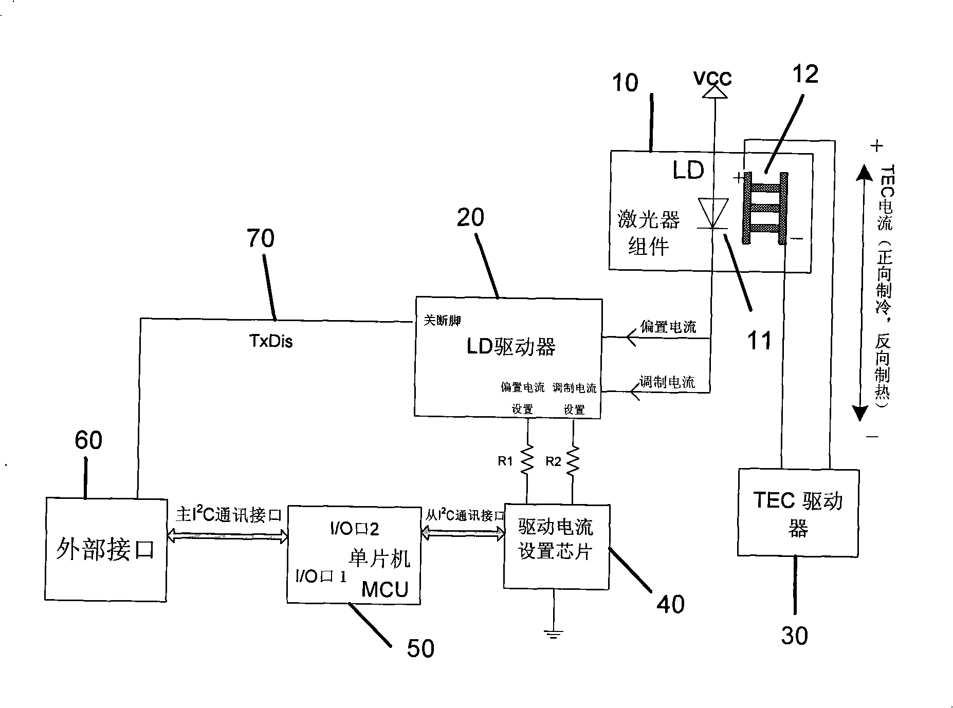
[0016] like Figure 4 The shown laser driving circuit includes a laser assembly 100, which is integrated by a laser diode LD110 and a thermoelectric cooler TEC120, the anode of the laser diode LD110 is connected to the power supply Vcc, and the cathode is connected to an LD driver 200 as the bias current and The modulation current conduction path, the thermoelectric cooler TEC120 is connected to a TEC driver chip 300, and the bias current setting terminal and the modulation current setting terminal of the LD driver 200 are connected to a driving current setting chip 400, wherein the driving current setting chip 400 can be Digital-to-analog conversion chip DAC or digital potentiometer. The drive current sets the chip 400 through the slave I 2 The C communication interface or other bus interface is connected with a single chip MCU500, and t...


PUM


Abstract

The invention provides a drive circuit of a laser, which comprises a laser component and an LD drive; wherein, the laser component is connected with a bias current output terminal and a modulated current output terminal of the LD drive, and a bias current set terminal and a modulated current set terminal of the LD drive are connected with a drive current set chip which is connected with a singlechip MCU through an I<2>C communication interface; the singlechip is connected with a turn-off pin of the LD drive through an interface 2 of a second interface I/O to control drive and enable LDDDis, and is also connected with an external interface through a main I<2>C communication interface; the emission of the external interface enables TxDis and is connected with an interface 1 of a first interface I/O of the singlechip, the state of TxDis enabled by emission can be distinguished by the singlechip MCU through the interface 1 of the first interface I/O, and the state of the drive current set terminal of the drive current set chip is controlled according to the state of the TxDis enabled by emission. Therefore, wavelength shift of the laser is reduced to achieve the requirements for the stability of the wavelength of the laser when a DWDM system is applied.

Description

technical field [0001] The invention relates to a laser driving circuit in a dense wavelength division multiplexing DWDM data transmission system, in particular to a laser driving circuit. Background technique [0002] In a dense wavelength division multiplexing (DWDM) data transmission system, the channel spacing of optical signals of different wavelengths becomes smaller and smaller as the density of the multiplexed channels increases. In order to ensure that the lights of the mutual channels do not collide, the wavelength of the transmitting end needs to maintain high stability. For example, in a 100GHZ DWDM system, the interval between adjacent channels is only 0.8nm. The system supplier requires the emission wavelength to be between λc-0.1nm and λc+0.1nm, and the instantaneous wavelength when the laser is turned on and off is Within the range of λc-0.2nm~λc+0.2nm. The usual DWDM laser driver circuit such as figure 1 As shown, the laser assembly 10 integrates a laser ...

Claims


Application Information

Patent Timeline
IPC IPC(8): H04B10/155H01S5/042H01S5/062H04B10/12
Inventor 黄伟毅姚海军夏京盛
Owner APAT OPTOELECTRONICS COMPONENTS
Why Eureka
Try Eureka