Cooling structure for working vehicle

A cooling structure and vehicle technology, which is applied to the cooling of the engine, the combined arrangement of the cooling of the power plant, and vehicle components, etc., and can solve problems such as increased noise, reduced heat dissipation, and increased operating speed of the air-cooling fan F

Active Publication Date: 2011-04-20
KOMATSU LTD
View PDF1 Cites 0 Cited by
  • Summary
  • Abstract
  • Description
  • Claims
  • Application Information

AI Technical Summary

Problems solved by technology

[0010] In this way, in the existing cooling system, since a large gap c is formed between the ventilation opening So of the cover S and the air-cooling fan F, the supply efficiency of the cooling air from the air-cooling fan F to the cover S is reduced. The amount of heat dissipation (cooling heat) is reduced, and the operating speed of the air-cooling fan F will increase due to supplementing the reduced amount, which will cause an increase in noise. In addition, if the operating speed of the air-cooling fan is not increased, A cooling system with a large heat dissipation is required, and a larger installation space needs to be designed, so there is a problem of increasing the cost of the cooling system

Method used


Image

  • Cooling structure for working vehicle
  • Cooling structure for working vehicle
  • Cooling structure for working vehicle

Examples


Embodiment Construction

[0053] Hereinafter, the present invention will be described in detail based on drawings showing embodiments.

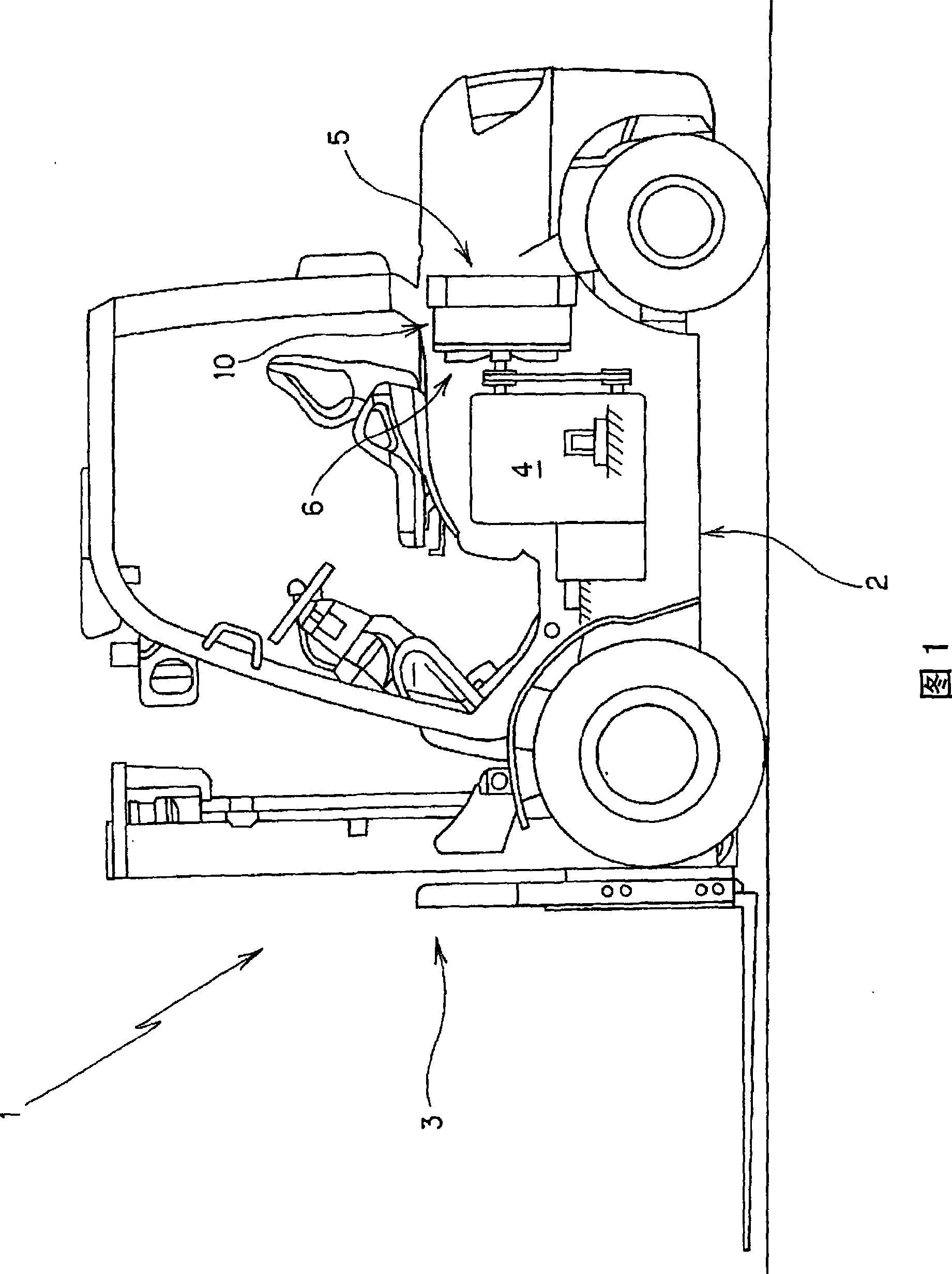
[0054] Figure 1 and figure 2 This is an example in which the present invention is applied to a fork-lift truck, which is one type of working vehicle, and the fork-lift truck 1 includes a vehicle body 2 and a working machine 3 installed in front of the vehicle body 2 .

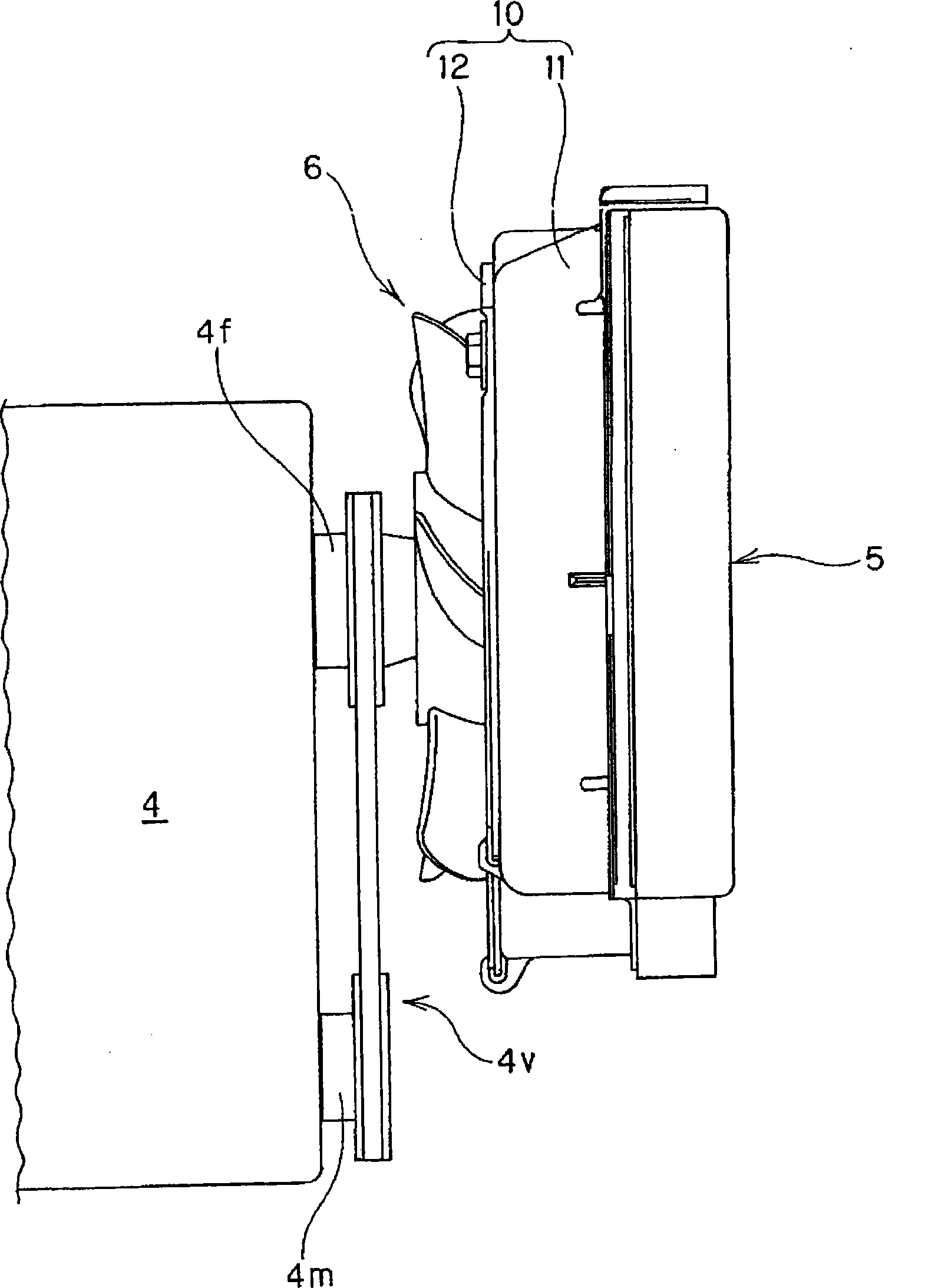
[0055]An engine 4 and a radiator 5 are mounted inside the vehicle body 2. The engine 4 is floatingly supported in the approximate central region of the vehicle body 2 via vibration-proof members such as rubber brackets. Describe the rear area of ​​the engine 4.

[0056] The air-cooling fan 6 is rotatably supported at the rear of the engine 4 via a fan shaft 4f, and the fan shaft 4f is connected to the main drive shaft (output shaft) 4m via a transmission mechanism 4v, whereby the air-cooling fan 6 follows Rotation is driven by the operation of the engine 4 .

[0057] In the front area relative to t...


PUM


Abstract

A cooling structure for a vehicle, where a shroud is attached to a radiator mounted on the vehicle and a cooling air fan is installed facing an airflow opening of the shroud. The shroud has a shroud body, an opening member having the airflow opening, and fastening means capable of fixing the opening member to the shroud body and capable of adjusting the position at which the opening member is fixed to the shroud body. The construction allows the relative positions between the cooling air fan and the airflow opening in the shroud to be adjustable, and as a result, the radiator has sufficient amount of heat radiation without causing disadvantage such as an increase in noise.

Description

technical field [0001] The present invention relates to a cooling structure for a working vehicle, which is configured by attaching a cover to a radiator mounted on a vehicle body, and making an air cooling fan of an engine mounted on the vehicle body face a ventilation opening provided on the cover. And formed. Background technique [0002] Figure 14 and Figure 15 The shown forklift truck (forklift) A, which is one type of working vehicle, includes a body B and a working machine W installed in front of the body B, and an engine E and a Radiator R and other equipment. [0003] Here, in order to improve the cooling efficiency of the radiator, a cooling system (cooling structure) in which a cover is attached to the radiator and the cooling air is concentrated has been proposed (for example, refer to Patent Document 1). [0004] That is, in Figure 14 and Figure 15 In the shown fork-lift truck A, a cover S having a ventilation opening So is attached to the front of the r...

Claims


Application Information

Patent Timeline
Patent Type & Authority Patents(China)
IPC IPC(8): F01P11/10B60K11/04
CPCB60K11/04F01P5/06F01P11/10B60Y2200/15
Inventor 伊藤真一郎加藤伸一川上拓史
Owner KOMATSU LTD
Why Eureka
Try Eureka