Direct drive type oil servo motor based on direct drive type electrohydraulic servo power source

An electro-hydraulic servo, direct-drive technology, applied in engine components, machines/engines, mechanical equipment, etc., can solve the problems of low efficiency and high failure rate, avoid overflow loss, improve reliability, and reduce the probability of failure Effect

Inactive Publication Date: 2009-04-22
HARBIN INST OF TECH +1
View PDF0 Cites 8 Cited by
  • Summary
  • Abstract
  • Description
  • Claims
  • Application Information

AI Technical Summary

Problems solved by technology

[0005] The purpose of the present invention is to overcome the disadvantages of the existing oil motor, such as the electro-hydraulic servo valve inevitably stuck, high failure rate and low efficiency due to the long-term work of the electro-hydraulic servo valve, and to provide a direct-drive oil motor based on the direct-drive electro-hydraulic servo power source. motivation

Method used


Image

  • Direct drive type oil servo motor based on direct drive type electrohydraulic servo power source
  • Direct drive type oil servo motor based on direct drive type electrohydraulic servo power source
  • Direct drive type oil servo motor based on direct drive type electrohydraulic servo power source

Examples


specific Embodiment approach 1

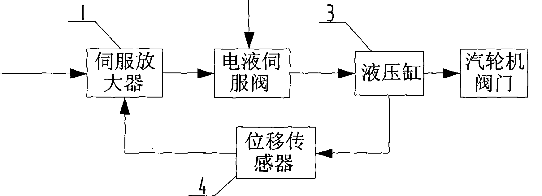
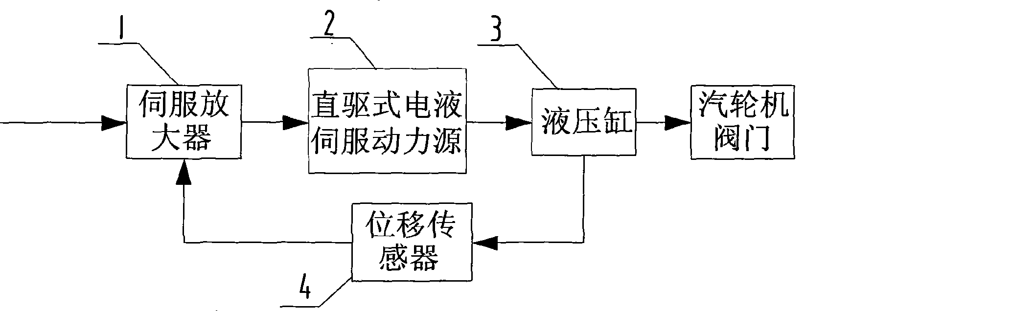
[0009] Specific implementation mode one: combine figure 2 and image 3 Describe this embodiment. This embodiment is composed of a servo amplifier 1, a direct-drive electro-hydraulic servo power source 2, a hydraulic cylinder 3 and a displacement sensor 4; the digital electro-hydraulic control system inputs the set oil motor stroke signal into the oil motor Servo amplifier 1 and displacement sensor 4 measure the feedback signal of the real-time displacement of hydraulic cylinder 3 to servo amplifier 1. Servo amplifier 1 compares and amplifies the two signals and outputs them to direct-drive electro-hydraulic servo power source 2. The hydraulic servo power source 2 drives the hydraulic cylinder 3 to move after receiving the electric control signal from the servo amplifier 1, and controls the opening and closing of the steam turbine valve and the opening degree of the valve. When the error between the position signal of the hydraulic cylinder 3 fed back by the position sensor 4...

specific Embodiment approach 2

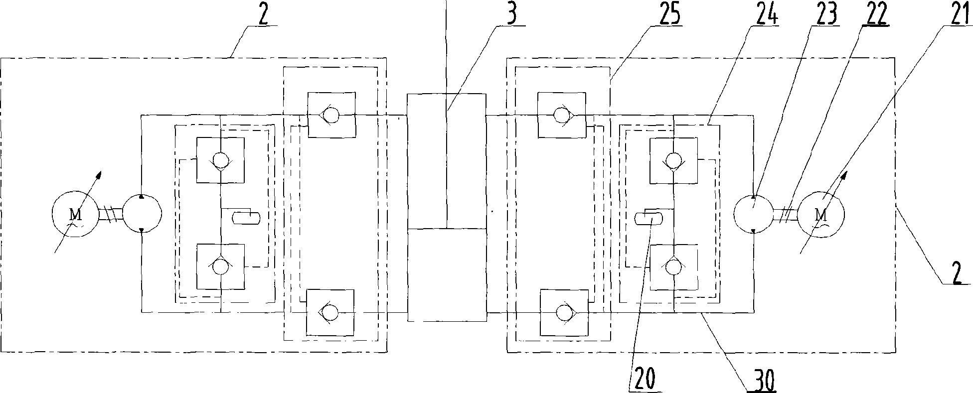
[0010] Specific implementation mode two: combination image 3 This embodiment is described. The difference between this embodiment and the first embodiment is that two sets of direct-drive electro-hydraulic servo power sources 2 are used to connect to the hydraulic cylinder 3 . Two sets of direct-drive electro-hydraulic servo power source 2 are connected in parallel at the inlet and outlet of hydraulic cylinder 3 to realize redundant configuration; when the steam turbine valve is opened and the opening is adjusted, a set of direct-drive electro-hydraulic servo power source 2 is used to work, When the air valve is closed, two sets of direct-drive electro-hydraulic servo power sources 2 work simultaneously to speed up the closing speed of the air valve. When one set of direct-drive electro-hydraulic servo power source 2 fails, the system automatically switches to the second set of direct-drive electro-hydraulic servo power source 2 to ensure the normal operation of the oil motor...

specific Embodiment approach 3

[0011] Specific implementation mode three: combination image 3 This embodiment is described. The difference between this embodiment and specific embodiment 1 is that the replenishment valve 24 is composed of two hydraulic control check valves, and the two hydraulic control check valves are respectively the first hydraulic control check valve and the second hydraulic control check valve. control check valve; one oil port and the control oil port of the first hydraulic control check valve are respectively connected with the two oil passages between the two-way quantitative pump 23 and the hydraulic cylinder 3, and one oil port of the second hydraulic control check valve The connection mode of the control oil port is opposite to the connection mode between one oil port and the control oil port of the first hydraulic control check valve, and the other oil port of the first hydraulic control check valve is connected to the other port of the second hydraulic control check valve. Th...


PUM


Abstract

The invention discloses an electrohydraulic servo power source-based direct drive servo motor and relates to a servo motor. The direct drive servo motor overcomes the drawbacks of the prior art of inevitable clamping stagnation, high fault rate and low efficiency due to long-term operation of an electrohydraulic servo valve. The direct drive servo comprises a direct drive electrohydraulic servo power source which comprises a closed oil tank, an alternating current servo motor, a bidirectional fixed displacement pump, an oil supplement valve and a bidirectional hydraulic lock, wherein a power outlet shaft of the alternating servo motor is connected with a power inlet shaft of the bidirectional fixed displacement pump which is connected with a hydraulic cylinder through the bidirectional hydraulic lock, two oil lines between the bidirectional fixed displacement pump and the hydraulic cylinder form a closed circuit, two oil inlet and outlet openings of the oil supplement valve are connected to the two oil lines between the bidirectional fixed displacement pump and the hydraulic cylinder respectively, a third oil inlet and outlet opening is connected with an oil inlet and outlet opening of the closed oil tank. The direct drive servo motor is used on an actuating mechanism of a steam turbine regulating and safety system and has the advantages of high reliability, energy conservation and high efficiency.

Description

technical field [0001] The invention relates to a regulating system of a steam turbine, in particular to an oil motor. Background technique [0002] The oil motor is the executive mechanism of the steam turbine regulation and security system. It accepts the instructions issued by the digital electro-hydraulic control system (DEH) to control the opening, closing and opening of the steam turbine inlet valve, so as to control the speed and load of the unit and protect the safety of the unit. Purpose. [0003] The schematic diagram of the traditional steam turbine oil motor system is as follows: figure 1 shown. The oil motor is composed of servo amplifier 1, electro-hydraulic servo valve, hydraulic cylinder 3 and displacement sensor 4 (LVDT). Among them, the stroke signal of the input oil motor and the feedback signal of the displacement sensor 4 are compared and amplified by the servo amplifier 1, and then output to the electro-hydraulic servo valve. After receiving the elec...

Claims


Application Information

Patent Timeline
Patent Type & Authority Applications(China)
IPC IPC(8): F01D17/26
Inventor 姜继海陈建华苏文海万保中常虹何寥刘庆和
Owner HARBIN INST OF TECH
Why Eureka
Try Eureka