Turbine type flow sensor for oil field well cementing

A flow sensor and turbine-type technology, applied in the field of flow sensors, can solve problems such as measurement errors and affecting cementing quality, and achieve the effects of small measurement errors, ensuring cementing quality, and simple structure

Inactive Publication Date: 2009-04-22
天津市大港仪表有限公司
View PDF3 Cites 2 Cited by
  • Summary
  • Abstract
  • Description
  • Claims
  • Application Information

AI Technical Summary

Problems solved by technology

At present, the installed turbine flow sensor usually uses a half-shaft turbine assembly. During the cementing mud metering process, due to the non-concentric half-shaft turbine assembly, it is easy to cause measurement errors, thereby affecting the cementing quality.

Method used


Image

  • Turbine type flow sensor for oil field well cementing

Examples


Embodiment

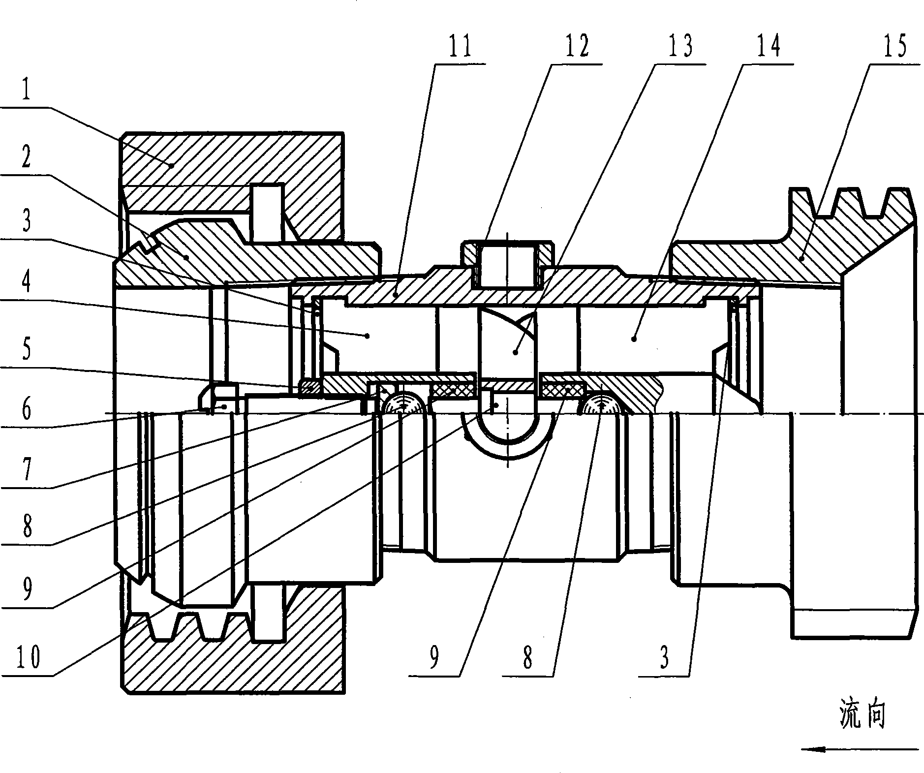
[0013] A turbine-type flow sensor for oil field cementing, consisting of a body 11, a shaft-through turbine assembly, an inlet guide frame 14, an outlet guide frame 4, an inlet joint and an outlet joint; the body 11 is a cylindrical metal tube The shaft-through turbine assembly includes a turbine 13, a turbine shaft 10, a shaft sleeve 9, a steel ball 8, a steel ball pad 7, an adjusting bolt 6, a spring retainer ring 3 and a lock nut 5, and the turbine 13 is fixed to the turbine shaft 10, two The bushings 9 are located on both sides of the turbine 13 and are closely matched with the inner holes of the inlet and outlet guide frames 14 and 4 respectively. Two steel balls 8 are respectively located at the two ends of the turbine shaft 10 and limit the turbine shaft 10. The steel ball 8 on the side is positioned by the round hole on the inlet guide frame 14, the steel ball 8 on the outlet side is located in the round hole of the outlet guide frame 4 and the position of the steel bal...


PUM


Abstract

The invention discloses a turbine flow sensor used in well cementing of an oil field. The turbine flow sensor consists of a sensor body, a through-shaft turbine assembly, an inlet flow guide frame, an outlet flow guide frame, an inlet joint and an outlet joint. The sensor body is a cylindrical metal tube; the through-shaft turbine assembly comprises a turbine, a turbine shaft, a shaft sleeve, steel balls, a steel ball cushion, an adjusting bolt, a spring retaining ring and a lock nut; the through-shaft turbine assembly is fixed in the sensor body by the inlet flow guide frame and the outlet flow guide frame; the inlet joint and the outlet joint are respectively a detachable structure and are hermetically connected with two ends of the sensor body by screw threads; and the sensor body is provided with a signal amplifier interface. The turbine flow sensor has the advantages of having high concentricity, tiny measurement error, simple structure and low fabrication cost by using the through-shaft turbine assembly, achieving fast and convenient disassembly by using the detachable interface, greatly prolonging the service life by the shaft sleeve made of polyurethane, accurately monitoring the flow rate of the injected slurry and assuring the quality of the well cementation by accessing a signal detection amplifier and a secondary instrument which are set according to a magnetic force line cutting principle.

Description

(1) Technical field [0001] The invention relates to a flow sensor, in particular to a turbine flow sensor for oil field cementing. (2) Background technology [0002] In oilfield exploration and development, every exploration and development of an oil well, from exploration to final cementing, it is necessary to inject mud into the casing and use the mud to seal the casing well, so as to ensure the service life of oil and gas development. Accurate measurement of the flow rate of injected mud is related to the cementing quality of each well. At present, the installed turbine flow sensor usually uses a half-shaft turbine assembly. During the cementing mud metering process, due to the non-concentric half-shaft turbine assembly, it is easy to cause measurement errors, thereby affecting the cementing quality. (3) Contents of the invention [0003] The object of the present invention is to solve the above existing problems, and provide a turbine type flow sensor for oilfield cem...

Claims


Application Information

Patent Timeline
Patent Type & Authority Applications(China)
IPC IPC(8): G01F1/32E21B33/13
Inventor 刘玲照宋兴风刘呈林刘呈森宋兴起刘同照魏殿祥程砚林
Owner 天津市大港仪表有限公司
Why Eureka
Try Eureka